This is default featured slide 1 title

Go to Blogger edit html and find these sentences.Now replace these sentences with your own descriptions.

This is default featured slide 2 title

Go to Blogger edit html and find these sentences.Now replace these sentences with your own descriptions.

This is default featured slide 3 title

Go to Blogger edit html and find these sentences.Now replace these sentences with your own descriptions.

This is default featured slide 4 title

Go to Blogger edit html and find these sentences.Now replace these sentences with your own descriptions.

This is default featured slide 5 title

Go to Blogger edit html and find these sentences.Now replace these sentences with your own descriptions.

Mostrando postagens com marcador mikrotik. Mostrar todas as postagens

domingo, 6 de março de 2022

Mikrotik - Getting IPv6 Going on RouterOS 7.1


As before, prerequisite is that you get at least /64 prefix from your ISP (Comcast in my case) via DHCPv6. Also assumed is empty IPv6 configuration.

The first thing I like doing is disabling the default neighbor discovery interface. Blasting IPv6 router advertisements on all interfaces is not necessarily a good idea:

Terminal
/ipv6 nd
set [ find default=yes ] disabled=yes

The next step is to setup DHCP client. Within a few seconds, you should see the prefix being allocated:

Terminal
/ipv6 dhcp-client
add add-default-route=yes interface=ether1 pool-name=general-pool6 request=prefix use-peer-dns=no

:delay 5s
print
Flags: D - dynamic, X - disabled, I - invalid
# INTERFACE STATUS REQUEST PREFIX
0 ether1 bound prefix 2601:db8:9780:ee2c::/64, 3d14h41m41s

At this time I love to allocate address ending with ::1 to the router itself:

Terminal
/ipv6 address
add address=::1 from-pool=general-pool6 interface=bridge1 advertise=yes

Now it should be possible to ping its address from external computer (in this example address would be 2601:db8:9780:ee2c::1). If this doesn’t work, do check if you have link-local addresses. If none are present, reboot the router and they will be regenerated.

With router reachable, it is time to delegate IPv6 prefix to internal machines too. For this purpose, setup RA (router announcement) over the bridge. While default interval settings are just fine, I like to make them a bit shorter (20-60 seconds):

Terminal
/ipv6 nd
add interface=bridge1 ra-interval=20s-60s

And that’s all. Now your computers behind the router will have direct IPv6 route to the Internet. Do not forget to setup both router firewall and firewall of individual devices. There is no NAT to save your butt here.

PS: Here is the basic IPv6 firewall allowing all connections out while allowing only established back in:

Terminal
/ipv6 firewall filter

add chain=input action=drop connection-state=invalid comment="Drop invalid"
add chain=input action=accept connection-state=established,related comment="Accept established"
add chain=input action=accept in-interface=ether1 protocol=udp src-port=547 limit=10,20:packet
add chain=input action=drop in-interface=ether1 protocol=udp src-port=547 comment="Drop ext DHCP >10/sec"
add chain=input action=accept in-interface=ether1 protocol=icmpv6 limit=10,20:packet
add chain=input action=drop in-interface=ether1 protocol=icmpv6 comment="Drop ext ICMP >10/sec"
add chain=input action=accept in-interface=!ether1 protocol=icmpv6 comment="Accept internal ICMP"
add chain=input action=drop in-interface=ether1 comment="Drop external"
add chain=input action=reject comment="Reject everything else"

add chain=output action=accept comment="Accept all"

add chain=forward action=drop connection-state=invalid comment="Drop invalid"
add chain=forward action=accept connection-state=established,related comment="Accept established"
add chain=forward action=accept in-interface=ether1 protocol=icmpv6 limit=20,50:packet"
add chain=forward action=drop in-interface=ether1 protocol=icmpv6 comment="Drop ext ICMP >20/sec"
add chain=forward action=accept in-interface=!ether1 comment="Accept internal"
add chain=forward action=accept out-interface=ether1 comment="Accept outgoing"
add chain=forward action=drop in-interface=ether1 comment="Drop external"
add chain=forward action=reject comment="Reject everything else"
fonte: https://www.medo64.com/2022/01/getting-ipv6-going-on-routeros-7-1/

sábado, 4 de janeiro de 2020

Mikrotik - em um carro de corrida


Assista no ponto de 3:00

sexta-feira, 4 de maio de 2018

Mikrotik - Block Bittorrent and P2P using latest Mikrotik Version 6.41

Mikrotik new version software stops blocking torrents and p2p with the error P2P matcher is obsolete please use layer7 matcher instead - MikroTik

Here are the new and revise configuration steps that will block torrents and p2p traffic from mikrotik router.

/ip firewall layer7-protocol
add comment="Block Bit Torrent" name=layer7-bittorrent-exp regexp="^(\\x13bitt\
    orrent protocol|azver\\x01\$|get /scrape\\\?info_hash=get /announce\\\?inf\
    o_hash=|get /client/bitcomet/|GET /data\\\?fid=)|d1:ad2:id20:|\\x08'7P\\)[\
    RP]"

/ip firewall filter
add action=add-src-to-address-list address-list=Torrent-Conn \
    address-list-timeout=2m chain=forward layer7-protocol=\
    layer7-bittorrent-exp src-address=192.168.2.0/24 src-address-list=\
    !allow-bit
add action=drop chain=forward dst-port=\
    !0-1024,8291,5900,5800,3389,14147,5222,59905 protocol=tcp \
    src-address-list=Torrent-Conn
add action=drop chain=forward dst-port=\
    !0-1024,8291,5900,5800,3389,14147,5222,59905 protocol=udp \
    src-address-list=Torrent-Conn 


fonte: https://www.mansooryousaf.com/blogs/block-bittorrent-and-p2p-using-latest-mikrotik-version-6-41

quinta-feira, 11 de janeiro de 2018

Disabling Mikrotik Hotspot DNS Proxying for Authenticated Users


My wireless ISP (WISP) uses the Mikrotik hotspot feature with RADIUS on the back end to authenticate our users. This implements a captive portal that redirects all DNS requests so that the user is taken to a login page if they’re not logged in. Once they log in once, the system associates their radio with their account, and they don’t have to log in anymore under normal circumstances.
However, once logged in, users still have all their DNS requests proxied through the routers. A lot of users want to use their own DNS (like OpenDNS or Google Public DNS), and that’s fine with me, but a user ran the namebench utility and found that their DNS was being forcibly proxied.
It took some hunting, but I finally found this post on the Mikrotik forums which details how to get around this. Basically:
  • The hotspot adds dynamic DNS redirect rules. If you go to /ip firewall nat and just print, these rules don’t show up. If you do print dynmic they do. The relevant lines are:

    2 D chain=hotspot action=redirect to-ports=64872 protocol=udp dst-port=53 log=no log-prefix=""
    3 D chain=hotspot action=redirect to-ports=64872 protocol=tcp dst-port=53 log=no log-prefix=""
  • We still want non-logged-in-users to have their DNS redirected, so we need to add something here that will enable authenticated hotspot users through. The magic incantation here (because it’s entries 2 and 3) is set 2,3 hotspot=!auth, which results in the following:

    2 D chain=hotspot action=redirect to-ports=64872 protocol=udp hotspot=!auth dst-port=53 log=no log-prefix=""
    3 D chain=hotspot action=redirect to-ports=64872 protocol=tcp hotspot=!auth dst-port=53 log=no log-prefix=""
And now namebench works as expected.

segunda-feira, 18 de dezembro de 2017

Link - implementação Daloradius em Raspberry (avaliando pra ver se presta)

https://github.com/pihomeserver/Kupiki-Hotspot-Script

quinta-feira, 14 de dezembro de 2017

Mikrotik - Change firewall rule order by script or cli

Managing Mikrotik firewall through CLI/SSH interface

Change firewall rule order

One of the bad things in Mikrotik firewall is that when you add new rule, it’s automatically applied at the end of the chain, which in most of the times has NO EFFECT. So you need to fine-tune your rule position in order to make it work as supposedd
First print the current rules
/ip firewall filter print without-paging
Now change the order, for example make rule number 18 to be number 1:
/ip firewall filter move 18 1


- comments by forum
After some VERY frustrating experiences with this task i stumbled upon this:
https://gryzli.info/2015/01/18/mikrotik ... ll-by-cli/

You MUST do /ip firewall filter print before actually moving the rule. Useless to say it's annoying when running batches with dsh or putty.
So you rsc would be:
/ip firewall filter print
/ip firewall filter move [find where comment ="blabla"] destination=32

Or in a single line: '/ip firewall filter print; /ip firewall filter move [find where comment ="blabla"] destination=32'


quinta-feira, 12 de outubro de 2017

Mikrotik - Password Recovery

Howto Recover Mikrotik ADMIN account Forgotten Password


49 Votes

Last Updated: 18th April, 2014, 22:04 gmt+5
According to information on Mikrotik WIKI and forums, it is not possible to recover the passwords without resetting whole mikrotik box (resulting in loss of all configuration also). However following are few methods to recover the password.
0# Recover password from BACKUP file using a website https://www.mikrotikpasswordrecovery.net/
If you require it on urget basis, you can email me your config, and I will recover it for you, just in case if you dont have linux or urgency is required.
1# Recover password from BACKUP file using Ubuntu or Linux LIVE CD [updated April 2014]

2# Recover password by mounting Mikrotik Hard disk in Linux LIVE CD  and do recovery [not updated since last year, it was tested with 5 version)


2# Recover password from BACKUP file using Linux [working as of april 2014]

Login to your Ubuntu / Linux Box,
Download mikrotik password recovery tool and compile it by following commands,
1
2
3
4
5
6
7
8
9
10
11
sudo apt-get update
sudo apt-get install build-essential g++ libssl-dev libcurl4-gnutls-dev libexpat1-dev gettext libz-dev
mkdir /temp
cd /temp
tar jxvf mtpass-0.9.tar.bz2
cd mtpass-0.9
make
 
#If you receive *error* after issuing make command, then you can use following command to compile it in desi JUGAAR (workaround) way hehehehe
g++ mtpass.cpp -lgnutls-openssl -o mtpass
Now upload/copy your Mikrotik Backup File to /temp folder ( Either using WINSCP gui tool, WEBMIN File Manager,  via USB or any other method you like)
Now Issue the following command
1
./mtpass /temp/zaibmikrotik.backup
It will show you all account passwords in few seconds.
As shown in the image below . . .
mtpass.
.
.

3# Recover password of x86 PC Version

Boot from Ubuntu LIVE CD
(I used Ubuntu 9.1 Desktop CD in this example, you can download it from following link.
Select “Try Ubuntu
As Shown in the image below . . .

After you see Desktop, Open TERMINAL from APPLICATION > ACCESSORIES > TERMINAL
Now change to root user by
sudo su
Now check your partitions by issuing
fdisk -l
you will see something like below image.

You partition can be different, use your judgment to see what partition mt is in, either by mounting it one by one.
Now mount it any folder , for example
mkdir /temp
mount -t auto /dev/sda2 /temp
Now check its content by ls /temp and you will something like below image
*********************************************************
*********************************************************
Now Copy the ‘mikrotik password file’, (in newer ROS , it is located in /rw/store/user.dat) to USB flash drive, It will be used to decode the password.
(The USB flash drive should be ‘plug and play’ in Ubuntu Live. Just plug it in usb port and it will appear on desktop in few seconds , OR you can also copy it your network pc via configuring interface lan card accordingly)
(Note: In older ROS it is /nova/store/user.dat)
Now shutdown live cd.
then Boot from your Ubuntu box, and use the Method # 2 , described earlier in this article to decode password using mtpass tool  from this file.
Copy the user.dat file where you have decompressed mt password tool . e.g /temp , now use the mt pass tool to recover password from this file.
./mtpass user.dat
and you will see your admin password.

As Now you have seen the password now, you can login into mikrotik pc router  with your Old Password  


If your architecture is ROUTERBOARD RB series, Please follow the below guide.
http://manio.skyboo.net/mikrotik/
Also it’s possible for you to send an SMS to your router, tell it to run a script (parameters supported) and the router can even respond, as it also supports SMS sending! More here:
http://wiki.mikrotik.com/wiki/Sms
You can setup an script just in case you forgot your password , and via sending sms, it can reset it to default. or send you return the new/original password.
Regard’s


fonte: https://aacable.wordpress.com/2012/01/14/howto-recover-mikrotik-admin-account-forgotten-password/

Nota: não testei nenhum destes metodos, nem sei se realmente funcionam.

terça-feira, 1 de agosto de 2017

Mikrotik - Reduce gaming and streaming lag with a Mikrotik RouterBOARD


Do you play online games? Of course you do. Have you experienced lag? Very likely. No matter how fast your internet connection is, if another program or person on your network competes for bandwidth, the packets will be processed at the same priority, resulting in increased latency (or worse, packet loss) for your game or other interactive applications. Whether you share an internet connection with roommates or operate a gaming house, LAN center, etc, this can quickly become a problem. Thankfully there's a cheap and relatively easy way to solve this in the form of a decent router - the Mikrotik RouterBOARD.
Many people are familiar with the trouble consumer grade routers can cause. It's not a surprise that the number one go to troubleshooting technique is a simple reboot - consumer routers are designed to be low price and thus operate on cheap hardware with limited memory which can easily cause problems. From NAT table overflows to DHCP server crashes, your off-the-shelf router probably isn't that great. While some routers claim to offer QoS options to help prioritize traffic, they have very limited functionality and can even reduce performance since the hardware in such routers is not meant for any kind of serious processing.
Thankfully there's a good step in between full grade business routers like Cisco (real Cisco, not the rebadged Linksys crap) and the off-the-shelf consumer routers. Mikrotik is a Latvian based company that produces both hardware (RouterBOARDs) and software (RouterOS) that provide a solid platform on which to build a router. The hardware alone is far and away better grade than almost anything you can find in consumer routers - try to find any big box retailer selling a router with 128 MB RAM! The software provides a GUI to a Linux-based routing setup - don't worry, you don't need to know any complicated Linux stuff - RouterOS handles it all for you, while still exposing all of the power and flexibility that Linux offers.
This guide is going to focus on setting up and configuring the RB951G-2HnD. This is one of the latest RouterBOARD models with a 600 MHz CPU, integrated high power 2.4GHz 802.11n wireless and five port gigabit ethernet. The RB951G-2HnD will handle up to around 200mbps internet connections without a problem.
Note: This guide is a work in progress.
Step 1: Buy It.
As RouterBOARDs are somewhat specialized hardware, you are unlikely to find many physical stores carrying them, so be prepared to order online. Depending on where you live, you have several options. In the US, the RB951G-2HnD is available at roc-noc.com, one of my favorite distributors (I've ordered many times from them with great results). It's also available on Amazon.
Outside of the US, I recommend consulting the Mikrotik distributor list to find a local seller.
Step 2: Unboxing and connecting
You'll receive a small box containing the router, a power adapter and possibly a sticker with your serial number on it. Don't expect any manuals or installation discs etc - remember these are not consumer routers! If you get a sticker, attach it to the bottom of your router for safe keeping. You shouldn't need to worry about the serial number unless you have to do a complete re-imaging of the RouterOS software.
Depending on your distributor, the default configurations for the device can vary. Typically the 1st ethernet port will be setup for WAN usage, and ports 2-5 LAN. Connect your internet (cable modem, fiber, DSL, etc) to port 1 and a PC or laptop to port 2 on the router using an ethernet cable, then plug in the power. The router should take around 15-30 seconds to boot. Now turn on your PC or laptop and it should hopefully acquire an IP address via DHCP from the router. The most common default range is 192.168.88.0/24, so expect an IP of 192.168.88.254 or similar. You should now be able to navigate to http://192.168.88.1/ to access "Webbox" - a cut down web interface version of "Winbox", a software program used to configure RouterOS. On the Webbox screen should be a link to download Winbox - click that and you should have a copy of winbox.exe which we will use for the rest of this guide.
Note: RouterOS runs on top of a full Linux OS. As such, you should avoid abruptly unpowering the router where possible as you run a small risk of causing file system corruption. In both Webbox and Winbox is a system / shutdown option which you can use to initiate a clean shutdown, at which point it is safe to remove power.
Step 3: Check for software updates
As the router has likely been sitting around in a warehouse for a few months, it's important to update the software to ensure you have the latest security and performance updates. To do this, log in to the router using the winbox.exe you downloaded - enter the IP address 192.168.88.1, username admin and a blank password.
Once logged in to winbox, on the left menu choose System / Packages and click "Check for updates". If an update is available, hit "Download and install" and your router will reboot and install the update.
Step 4: Configure wireless network
Now let's set up your wireless network. On the Wireless menu in winbox, double click on wlan1 to open up the properties for the wireless adapter. From here, go to the "Wireless" tab and hit the "Advanced Mode" button, then set the following options:
Wireless Protocol: 802.11
Frequency Mode: regulatory domain
Country: Your country
Channel Width: 20/40 MHz Ce
Frequency: Pick the least congested frequency - use the "Freq Usage" button as a quick test
SSID: Name of your wireless network
Hit OK, then go to the "Security Profiles" tab of the Wireless dialog. Double click "default" and set the following:
Mode: dynamic keys
Authentication Types: WPA2 PSK
Ciphers: aes ccm
WPA 2 Pre Shared Key: Your wireless password
This should leave you with a fully secured wireless network.
Step 5: Set up some basic features
Go to System / Clock and set your time zone (don't worry about the date / time)
Go to System / SNTP Client and enable it, set primary server time.nist.gov, secondary pool.ntp.org
Go to System / Password and enter a password to secure the router's admin interface
Go to IP / UPNP and hit Enabled. Click the Interfaces box, then click the + to add a new interface. Add ether1 (your internet) as an external interface. Hit OK, then + again and add bridge-local as your internal interface. This will enable UPNP allowing applications on your network to configure port forwarding automatically if needed.
At this point you are pretty much set if all you want is a solid, stable router. The next steps will set up QoS to ensure smooth gaming and streaming.
Step 6: Setting up QoS
This is where it starts to get a little complicated. Rather than explain everything involving the firewall, connection marking, packet tagging, queues, priorities, etc, I'm going to give you a bunch of commands that you should run. To run these commands, press "New Terminal" in winbox, then copy and paste the following:
/queue tree
add limit-at=9700k max-limit=9700k name=queue1 parent=ether1-gateway queue=default
add limit-at=9300k max-limit=9300k name=prio5-streaming packet-mark=streaming parent=queue1 priority=5 queue=default
add limit-at=100k max-limit=9500k name=prio8-untagged packet-mark=no-mark parent=queue1 queue=default
add limit-at=1G max-limit=1G name=prio3-gaming packet-mark=gaming parent=queue1 priority=3 queue=default
add limit-at=1G max-limit=1G name=prio2-misc-fast packet-mark=misc-fast parent=queue1 priority=2 queue=default
add limit-at=100k max-limit=9500k name=prio6-http packet-mark=http parent=queue1 priority=6 queue=default
/ip firewall mangle
add action=mark-packet chain=postrouting connection-mark=streaming new-packet-mark=streaming passthrough=no
add action=mark-packet chain=postrouting connection-mark=gaming new-packet-mark=gaming passthrough=no
add action=mark-packet chain=postrouting new-packet-mark=misc-fast packet-size=40 passthrough=no protocol=tcp tcp-flags=ack
add action=mark-packet chain=postrouting dst-port=53 new-packet-mark=misc-fast out-interface=ether1-gateway passthrough=no protocol=udp
add action=mark-packet chain=postrouting connection-mark=http new-packet-mark=http passthrough=no
add action=mark-connection chain=postrouting comment=Streaming connection-state=new dst-port=1935 new-connection-mark=streaming out-interface=ether1-gateway protocol=tcp
add action=mark-connection chain=postrouting comment=League dst-port=5000-5500 new-connection-mark=gaming out-interface=ether1-gateway protocol=udp
add action=mark-connection chain=postrouting comment=SC2 dst-port=1119 new-connection-mark=gaming out-interface=ether1-gateway protocol=udp
add action=mark-connection chain=postrouting comment=HotS dst-port=1120,3724 new-connection-mark=gaming out-interface=ether1-gateway protocol=udp
add action=mark-connection chain=postrouting comment="BW + HotS" dst-port=6112-6113 new-connection-mark=gaming out-interface=ether1-gateway protocol=udp
add action=mark-connection chain=postrouting comment="Valve Games" dst-port=27000-27060 new-connection-mark=gaming out-interface=ether1-gateway protocol=udp
add action=mark-connection chain=postrouting comment="Web Browsing" connection-state=new dst-port=80,443 new-connection-mark=http out-interface=ether1-gateway protocol=tcp
After doing this, click on Queues / Queue Tree and double click queue1. You'll see the value 9700k - this should be replaced by a little under your upload speed. The copy/paste code was designed for someone with 10mbps upload, so the maximum upload is limited to 9.7mbps (9700k). You want to limit it just under your max upload, otherwise there is a risk the upload will be queued on your modem, making all the QoS worthless. After setting your max upload on queue1, double click streaming and do the same, except slightly lower. If streaming affects your gaming, you can set the streaming queue to a little over your maximum stream bitrate so that the stream bandwidth is smoothed out, but try the regular method first.
Next up, double click http and no-mark and do the same there - replace 9500k with a number slightly less than the number you used for queue1. This will ensure http and uncategorized traffic won't hog the connection.
This will set up basic upload QoS, with supported games being StarCraft 2, Brood War, Valve Source based games (CS:GO, Dota 2, etc), Heroes of the Storm and League of Legends . Gaming and important small packets such as TCP acks and DNS get the highest priority, ensuring there's no lag even if the upstream is close to max. The next highest priority is outgoing stream data, so if you're streaming it won't get interrupted by other uploads such as video uploads or torrents.

fonte: https://r1ch.net/blog/routerboard

segunda-feira, 12 de junho de 2017

Mikrotik - PPPoE Server Configuration in MikroTik Router


PPPoE (Point to Point Protocol over Ethernet) is one of the most popular services in MikroTik Router. PPPoE is an extension of the standard Point to Point Protocol (PPP). The difference between them is expressed in transport method: PPPoE employs Ethernet instead of serial modem connection. PPPoE is a client-server protocol that means PPPoE client (IP devices such as Desktop, Laptop, wireless Router etc.) will request for IP information to PPPoE server providing security information (username and password) and PPPoE server will provide IP information by matching that security information.
PPPoE provides extensive user management, network management and accounting benefits to ISPs and network administrators. PPPoE is used mainly by ISPs to control client connections for xDSL and cable modems as well as plain Ethernet networks. PPPoE is now most popularly used in local ISP company because local ISP user can so easily be maintained with this service. So, this article is designed to show how to maintain ISP clients by configuring a PPPoE server in MikroTik Router.

ISP Setup with PPPoE Configuration

As a system administrator of an ISP company, you have to maintain various offered bandwidth packages such as 512kbps connection, 1Mbps connection, 2Mbps connection and so on. The users of these packages can so easily maintain with MikroTik PPPoE service. Now I’ll show you how to configure a PPPoE service in MikroTik router to maintain your various offered packages. But before starting configuration, I’ll show you a basic simple network diagram where a MikroTik router is serving as a PPPoE server.
PPPoE Network Diagram
In the above network diagram, MikroTik router WAN port (ether 1) is connected to internet and LAN port (ether 2, where we’ll configure PPPoE server) is connected to a distribution switch. PPPoE clients (PC, Laptop, Tablet and Wireless Router) are connected to the PPPoE server through this distribution switch. This is a basic and small network. In practical, your network will be an enterprise network where there may have thousands of clients. But the configuration will be almost same. Only the difference is that you might use multiple Ethernet ports for network simplicity, where we are using only one port here. You might use multiple WAN ports for handling load balancing or network redundancy where we are using only one WAN port here. I’ll discuss load balancing or network redundancy in my coming article. If you want to use multiple Ethernet ports for your LAN, you have to create MikroTik Bridge virtual interface for accumulating multiple interfaces into a single interface and then configure PPPoE server in that virtual interface.
As PPPoE is a client-server protocol, there are two end configurations for PPPoE service.
  1. PPPoE server configuration in MikroTik Router
  2. PPPoE client configuration
To run a PPPoE service in your network, first you have to configure PPPoE server in MikroTik router and then you have to learn how to configure various PPPoE clients.  In the rest of this article I’ll show you how to configure PPPoE server in MikroTik router and how to configure PPPoE client in windows operating system. However, I’ll recommend you that search in Google and learn how to configure PPPoE client in various operating platform.

5 Steps to Configure PPPoE Server in MikroTik Router

Now we are going to configure PPPoE server in MikroTik to maintain the clients of a Local ISP. Generally any ISP company has various offered packages depending on bandwidth.  It is always better to maintain client bandwidth with MikroTik Queues service although bandwidth can also be maintained with PPPoE service. Specially I‘ll recommend you to use MikroTik PCQ service which I have explained in my previous article about ISP bandwidth management with MikroTik PCQ to maintain your different bandwidth packages. Now we’ll use PPPoE server only for assigning different IP Block’s IP to different clients according to their bandwidth packages. For example, our proposed IP blocks for different bandwidth packages will be like below.
  1. 512kbps client will get 172.16.0.0/24 block IP
  2. 1Mbps client will get 172.16.1.0/24 block IP
  3. 2Mbps client will get 172.16.2.0/24 block IP
So, now we will configure our PPPoE server like that when a user purchase 512kbps connection, he/she will get a 172.16.0.0/24 block IP with his username and password. Similarly, when a user will purchase 1Mbps connection, he/she will get a 172.16.1.0/24 block IP and a 2Mbps user will get a 172.16.2.0/24 block IP. Complete PPPoE server configuration in MikroTik router can be divided into 5 steps.
  1. MikroTik router basic configuration
  2. IP Pool configuration
  3. PPPoE server configuration
  4. PPP profile configuration
  5. PPP secrets (username and password) configuration

Step 1. MikroTik Router Basic Configuration

MikroTik router basic configuration is the prerequisite to complete PPPoE server configuration. MikroTik router basic configuration includes assigning WAN and LAN IP addresses, Gateway configuration, DNS configuration and NAT configuration. If you are a new MikroTik user, feel free to spend some time to study my previous article about MikroTik router basic configuration using Winbox because how to configure MikroTik router from very beginning has been explained in that article. In this article, I assume that you have some knowledge about MikroTik router. So, if you are familiar with MikroTik router, follow below steps to complete MikroTik router basic configuration.
  1. Login to your MikroTik router using winbox software and go to IP > Addresses and then click on add new button (PLUS Sign). New Address window will appear now.
  2. In this window, put your WAN address that you have got from ISP company in Address field and choose ether1 or your WAN interface that like from Interface drop-down menu and then click Apply and OK button. WAN address will be assigned successfully.
  3. Again, click on add new button (PLUS Sign) and put your LAN address (in this article, I am using 172.16.0.1/24) in Address field and then choose your LAN interface from Interface drop-down menu. Now click Apply and OK button. LAN address will be assigned successfully.
  4. Now go to IP > DNS menu. DNS Settings window will appear. In this window, put DNS server address that you have got from ISP company or you can use Google’s public DNS IP (8.8.8.8) in Servers input box. You can put secondary DNS server IP by clicking add new value button located after the Servers input box. Optionally, you can turn your MikroTik router as a DNS server. Turning your MikroTik router as a DNS server is a better idea, I think. Because if you use public DNS server in your network, every DNS request of your user will consume your paid bandwidth. But if you turn MikroTik router as a DNS sever, your user will get DNS solution from MikroTik router without consuming your paid bandwidth. So, if you want to turn MikroTik as a DNS server, click the Allow Remote Requests check box and click Apply and OK button. Your MikroTik router is now a DNS server. All MikroTik IP addresses can now be used as a DNS server IP including WAN IP which is a public IP and problem will arise here. If anyone outside of your LAN use your WAN IP as a DNS IP, your MikroTik will be happy by serving him/her DNS solution consuming your paid bandwidth. So, for stopping DNS request from outside of your LAN, you should apply a firewall rule that will drop all DNS requests coming from your WAN interface (in this article, ether1). For this, go to IP > Firewall menu and click on add new button (PLUS Sign). New Firewall Rule window will appear now. Under General tab, choose Chain: input, Protocol: udp, Dst. Port: 53 and In. Interface: ether1. Now choose Action: drop from Action Tab and click Apply and OK button. Create another similar rule for TCP connection. Click on add new button (PLUS Sign) again and choose Chain: input, Protocol: tcp, Dst.Port: 53 and In. Interface: ether1 and then choose Action: drop under Action tab and click Apply and OK button. Now your MikroTik DNS server is safe from outside of your LAN.
  5. Go to IP > Routes menu for setting Gateway. From Route list window, click on add new button (PLUS). New Route window will appear now. Put your gateway address that you have got from your ISP in Gateway input field and click Apply and OK button. MikroTik default gateway will be assigned now.
  6. Now you have to create NAT rule so that your LAN user can access internet through your router. For this, go to IP > Firewall menu and click on NAT tab. Now click on add new button (PLUS Sign). New NAT Rule window will appear. Choose Chain: srcnat and Address: 172.16.0.0/16 under General tab and choose Action: masquerade from Action tab and then click Apply and OK button. Note that we are using all Class B IP blocks for masquerading because all our LAN IP block will be within this block.
MikroTik router basic configuration for configuring a PPPoE server will be completed if you follow the above steps carefully. If you face any problem to complete MikroTik router basic configuration, follow my video tutorial about MikroTik Router Basic Configuration using Winbox. I hope, it will reduce your confusion. Now we will do our second step about IP Pool configuration for configuring a PPPoE server successfully.

Step 2. IP Pool Configuration

We will now create three IP Pools because we assume that we have three offered packages and our user will get different IP block IP according to their package purchase. So, follow below steps to create IP Pools in your MikroTik router.
  1. Go to IP > Pool menu and click on add new button (PLUS Sign). New IP Pool window will appear now. Put Name: 512kbps_Pool and Addresses: 172.16.0.2-172.16.0.254 in New IP Pool window and click Apply and OK button. When a user will purchase a 512kbps connection, he/she will get an IP from this IP address range. Note that address range excludes the first IP because it will be used as a Gateway address.
  2. Similarly, create another two new IP Pool named as 1Mbps_Pool and 2Mbps_Pool and Address range will be 172.16.1.2-172.16.1.254 and 172.16.2.2-172.16.2.254 accordingly.
IP pool configuration has been completed. Now we’ll go our next step about PPPoE server configuration in MikroTik Router.

Step 3. PPPoE Server Configuration

Now we’ll configure our PPPoE server in MikroTik router. Follow bellow steps carefully for proper PPPoE server configuration in MikroTik router.
  1. Click on PPP menu item from left menu bar. PPP window will appear now. Click on PPPoE Servers tab and then click add new button (PLUS Sign). New PPPoE Service window will appear now. In this window, put your PPPoE server name (in this article I am giving Service Name ISP_PPPoE_Server) as you like in Service Name input box.
  2. Now choose your LAN interface where PPPoE server will be created from Interface drop-down menu. In this article, I am using ether1. If you create bridge interface, your bridge interface will be available in this list. So, choose bridge interface if you want to create PPPoE server in your bridge interface.
  3. Click on One Session Per Host If you left it blank, multiple host/devices can be connected with the same username and password. Obviously, you don’t want it.
  4. At the bottom of this window, you can see there are 4 authentication methods. Here only select PAP, and unselect all others. Now click Apply and OK
PPPoE server configuration in MikroTik router has been completed. Now we’ll create three profiles from where our clients will get IP address.

Step 4. PPP Profile Configuration

Now we will create there profiles those will be used by our clients for getting IP addresses. Follow below steps to create PPP profile in MikroTik router.
  1. Open PPP window by clicking PPP menu from MikroTik menu bar and then click on Profiles tab. You will see already two default profiles are created by MikroTik. We will do nothing these default profiles. We will create three new profiles here. For this, click on add new button (PLUS Sign). New PPP Profile window will appear now.
  2. In New PPP Profile window, put your profile name as you want in Name For simplicity, I am using 512kbps_Connection. Now put Local Address: 172.16.0.1 and choose 512kbps_Pool from Remote Address drop-down menu. Note that Local Address is the gateway address of this IP block which not included in 512kbps_Pool. So, when a 512kbps user will connect to this profile, he/she will get an IP from 512kbps_Pool and his/her gateway will be 172.16.0.1 that means this IP is one of the MikroTik IPs.
  3. At the bottom of this window, put MikroTik IP that you have used for Local Address (for this profile: 172.16.0.1) as DNS Server because we have turned our MikroTik router as a DNS server. Optionally, you can put another DNS server IP that you have got from your ISP or Google’s public DNS 8.8.8.8 by clicking add new value button located after DNS Server input box.
  4. Now click Apply and OK button.
  5. Similarly, create another two profiles for 1Mbps connection and 2Mbps connection. In this case, put 172.16.1.1 and 172.16.2.1 as Local Address and choose 1Mbps_Pool and 2Mbps_Pool for Remote Address
  6. Optionally, you can set limit for these users from Limits For this, click on Limits tab and put download and upload speed in Rate Limit (rx/tx) input box in bit. For example, type as 512000/512000 for this profile. My experience using this option is not so good. So, I’ll recommend to use MikroTik PCQ service for control user bandwidth.
PPP profile configuration has been completed. Now we will create user secret (username and password) so that they can connect to our PPPoE server with this secret.

Step 5.  PPP Secret Configuration

Now we will create secret that means username and password of a client by which he/she will be connected to our network. Follow bellow steps to create secrets of your clients.
  1. Open PPP window and click on Secrets New PPP Secret window will appear now.
  2. Put the username of any client in the Name input box and put password in Password input box. Note that username and password are necessary when any client will be connected from his workstation (PC, Laptop, Router and so on). Also, it is case-sensitive. So, be careful to put these field.
  3. Now choose Service: pppoe from Service drop-down list and choose profile for this user from Profile drop-down list. If this user purchase a 512kbps connection, choose 512kbps_Connection profile or choose the option according to the connection type of this user.
  4. Optionally, you can bind any device with this username and password by providing MAC address. For this, put MAC address of any device in Caller ID input box. If you put MAC address of any device in Caller ID, only this device can be connected with this secret (username and password).
  5. Do the above steps for all your clients and provide him/her username and password to connect to your PPPoE server.
PPP secret configuration has been completed as well as all the steps for configuring a PPPoE service in MikroTik router has been completed. Now I’ll show you how to configure PPPoE client in windows operating system in the rest of this article.

PPPoE Client Configuration

We have completely configured a PPPoE service in MikroTik router. Now your MikroTik is ready to accept PPPoE client. A number of PPPoE clients are present now a day. Among them, now I’ll show you how to configure PPPoE client in windows 7 operating system. All other versions of windows operating system follow almost the same procedure. So, you don’t face any difficulty, I think. However, if you feel any problem to configure PPPoE client of any operating platform, I recommend you to do Google and learn how to configure PPPoE client of that specific operating platform.
Steps to Create PPPoE dial Up Connection in Windows 7
Microsoft PC dialer is used to connect remote PPPoE server in window 7 to get access to the internet. So, you have to configure Microsoft PC dialer in windows 7 PC to get access to the internet through your MikroTik router. Follow my bellow steps to create PPPoE connection in windows 7 with built in PPPoE wizard.
  1. Connect an Ethernet cable to windows 7 PC from your network switch.
  2. Open Network and Sharing Center from Control Panel.
  3. Now click on Setup a new connection or network link under Change your networking settings area. Set Up a Connection or Network window will appear.
  4. In this window, click on Connect to the internet option and click the Next Connect to the Internet window will appear.
  5. Click on Broadband (PPPoE) option from this window and put username and password that you have created in PPP secret configuration step in User name and Password input field accordingly. Optionally, you can change connection name in Connection name input field and you can also click on Remember this password option otherwise you have to provide password every time you start your PC. Now click on Connect If you provide correct username and password, The connection to the Internet is ready to use message will be shown. Now click on Close button. A dialer will be created in your windows 7 PC and you can enter your credential anytime to connect Internet with this dialer.
You are now connected to the internet with PPPoE dialer. Browse any site. I hope, you will be successful to browse any site now.
PPPoE server configuration for a local ISP or a office network will be successful if you follow the above steps carefully. However, if you face any confusion to do above steps successfully, watch my below video about PPPoE server configuration in MikroTik router. I hope, it will help you to configure your PPPoE server successfully.
PPPoE server configuration in MikroTik router has been explained step by step in this article. Also, PPPoE client configuration in windows operating system has been shown here. I hope, you are now able to configure a PPPoE server in MikroTik router to maintain your ISP clients. However, if you face any problem to configure PPPoE service in MikroTik router, feel free to discuss in comment or contact with me form.


fonte:  http://systemzone.net/pppoe-server-configuration-in-mikrotik-router/

sexta-feira, 9 de junho de 2017

Mikrotik - MTU calculation on MikroTik


MTU calculation on MikroTik


Maximum Transmission Unit is a term in information technology refers to the size of the largest data packet that can be transmitted over a network medium. MTU size is variable, depending on the network technology used.An example is the network based on Ethernet technology, the maximum MTU size is 1500 bytes. It is the task of the data link layer must determine the size of the MTU.
Setting MTU is usually done on a kind of device networking switches, routers and so on. Very rarely do the MTU setting manually on a workstation or host. If the IP layer receives packets to be forwarded to the network, the device will calculate the size of the package if added to the 20 bytes ip header. If it turns out the package to be delivered has ukran MTU larger than the MTU device that receives the packet, the packet will be fragmented, or cut into smaller sizes.


MTU great value makes it possible to transmit data faster, imagine if you've got a lot of data is then collected into one big box. Then we simply send all the data one time using a large box. But if untukran small box, then we need to send a couple of times. MTU value are not then there is always a good effect. The longer the MTU, the more unreliable the data transmission process. If there is any damage in the delivery package, the whole package is damaged will be resubmitted by the TCP (Transmission Control Protocol).
So also on systems that MikroTik RouterOS which has a large MTU size standard of each interface. In RouterOS for MTU is divided into several types: MTU L3 (IP / Layer-3), L2.5 MTU (MPLS / Layer2.5), L2 MTU (MAC / Layer-2), Full Frame MTU. Of the types of MTU, has a different standard. 
  • L3 MTU = 1500 (Data: 1480 + IP: 20), 
  • L2.5 MTU = 1504 (Data: 1480 + IP: 20 + MPLS: 4)
  • L2 MTU = 1508 (Data: 1480 + IP: 20 + MPLS: 4 + VLAN: 4)
  • FULL Frame MTU = 1522 (Data: 1480 + IP: 20 + MPLS: 4 + VLAN: 4 + ETH: 14).
The big difference MTU value of each type depends on the type of traffic that will be handled. If the MTU size is only pegged at a value 1500 (L3 MTU) without adding any type of MTU The others then for traffic with the service VLAN, MPLS, it will not pass. In normal conditions the data packets that have a size too big to be in fragments by the device automatically. Too many packages are difragment will result in packet queue that is also long, and the device that receives the package also must rearrange received packets. MTU size supported Mikrotik products can be found here . 
Especially if there are applications that require static value of data packets, the network administrator should be able to determine the size of data packets to be passed so that the package can be received well. Some of the services that transmit data over the network will usually add a header to the data packet, for example ping.
At the time of data out of the device, the data packet will be coupled with some headers, such as IP Header 20bytes, and ICMP header 8bytes. To perform the test, you can use the ping command -s -f on windows OS, ping -M -s on Linux, or ping -D -s on Mac OSX. Suppose we try pinging the 1500 package size, without fragmentation.
That happened the destination device can not receive because of the size of the package is too large. Why so, when the opponent has the MTU setting of 1500. 1500 is the size of the data packet size before adding header. Then we can calculate the exact size of the data so that the ping packets can be received. 
1500 = 20 (IP header) + 8 (ICMP header) + Data
Data = 1500-20 (IP header) - 8 (ICMP header)
Data = 1472
If we try pinging the 1472 size, the packet can be received well 
Another service is usually also add a header to a specific value, such as VPN PPTP and PPPoE. This service will add pptp header and checksum, while adding PPPoE header PPPoE, PPP ID, DST and SRC Address. 
PPTP:
Data = 1500-20 (IP Header) - 28 (PPTP Header) - 2 (checksum) = 1450
PPPOE
1500-6 (PPPoE Header) - 2 (PPP ID) - 12 (DST and SRC Adress) = 1480 
Calculation as above also apply when using the service lainBisa concluded that by increasing the size of the IP header, then the size of the data on which ditrasmisikan also getting smaller. Miminum MTU size is 576 bytes.
Path MTU Discovery 
To determine the value of MTU devices opponent, device connected to the network has a mechanism called path MTU discovery. This mechanism did not membuthkan feature or special service, but uses a fairly simple way that is using the ICMP error reporting mechanism.
 
fonte: http://mikrotik234.blogspot.com.br/2017/03/mtu-calculation-on-mikrotik.html 

quarta-feira, 31 de maio de 2017

Mikrotik - Bandwidth Control (apesar de antigo, esta melhor explicado que o o wiki do fornecedor)

General Information


Summary

Bandwidth Control is a set of mechanisms that control data rate allocation, delay variability, timely delivery, and delivery reliability. The MikroTik RouterOS supports the following queuing disciplines:
  • PFIFO - Packets First-In First-Out
  • BFIFO - Bytes First-In First-Out
  • SFQ - Stochastic Fairness Queuing
  • RED - Random Early Detect
  • PCQ - Per Connection Queue
  • HTB - Hierarchical Token Bucket

Specifications

Packages required: system
License required: Level1 (limited to 1 queue) , Level3
Submenu level: /queue
Standards and Technologies: None
Hardware usage: significant

Description

Quality of Service (QoS) means that the router should prioritize and shape network traffic. QoS is not so much about limiting, it is more about providing quality service to the network users. Some features of MikroTik RouterOS traffic control mechanism are listed below:
  • limit data rate for certain IP adresses, subnets, protocols, ports, and other parameters
  • limit peer-to-peer traffic
  • prioritize some packet flows over others
  • use queue bursts for faster web browsing
  • apply queues on fixed time intervals
  • share available traffic among users equally, or depending on the load of the channel
The queuing is applied on packets leaving the router through a real interface (i.e., the queues are applied on the outgoing interface, regarding the traffic flow), or any of the 3 additional virtual interfaces (global-in, global-out, global-total).
The QoS is performed by means of dropping packets. In case of TCP protocol, the dropped packets will be resent on a slower rate, so there is no need to worry that with shaping we lose some TCP information.
The main terms used to describe the level of QoS for network applications, are:
  • queuing discipline (qdisc) - an algorithm that holds and maintains a queue of packets. It accumulates the packets and decides the order of the outgoing packets (it means that queuing discipline can reorder packets). Qdisc also decides which packets to drop if there is no space for them.
  • CIR (Committed Information Rate) - the guaranteed data rate. It means that traffic rate, not exceeding this value should always be delivered
  • MIR (Maximal Information Rate) - the maximal data rate router will provide
  • Priority - the order of importance in what traffic will be processed. You can give priority to some traffic in order it to be handeled before some other traffic
  • Contention Ratio - the ratio to which the defined data rate is shared among users (when a certain data rate is allocated to a number of subscribers). It is the number of subscribers that have a single speed limitation, applied to all of them together. For example, the contention ratio of 1:4 means that the allocated data rate may be shared between no more than 4 users
Before sending data over an interface, it is processed with a queuing discipline. There can be only one queueing discipline per interface, which, by default, is set under /queue interface for each physical interface (there is no default queuing discipline for virtual interfaces). Once we add a first queue (in /queue tree or /queue simple) to a physical interface, the interface default queue is replaced by HTB hierarchy with that queue, but the one defined in /queue interface for that particular interface, is no more active.
Scheduler and Shaper qdiscs
We can classify queuing disciplines by their influence to packet flow:
  • schedulers - queuing disciplines only reschedule packets regarding their algorithm and drop packets which 'do not fit in the queue'. Scheduler queuing disciplines are: PFIFO, BFIFO, SFQ, PCQ (both scheduler and shaper), RED
  • shapers - queuing disciplines that also perform the limitation. Shapers are PCQ (both scheduler and shaper) and HTB
Virtual Interfaces
There are 3 virtual interfaces in RouterOS, in addition to real interfaces:
  • global-in - represents all the input interfaces in general (INGRESS queue). Please note that queues attached to global-in apply to traffic that is received by the router, before the packet filtering. global-in queueing is executed just after mangle and dst-nat
  • global-out - represents all the output interfaces in general (EGRESS queue). Queues attached to it apply before the ones attached to a specific interface
  • global-total - represents a virtual interface through which all the data, going through the router, is passing. When attaching a qdisc to global-total, the limitation is done in both directions. For example, if we set a total-max-limit to 256000, we will get upload+download=256kbps (maximum)
Introduction to HTB
HTB (Hierarchical Token Bucket) is a classful queuing discipline that is useful for applying different handling for different kinds of traffic. The queues you add in /queue simple and /queue tree are attached to the main Hierarchical Token Bucket (HTB). For example, you can set a maximum data rate for a workgroup and then distribute that amount of traffic between the members of that workgroup.
HTB qdisc in detail:

HTB terms:
  • filter - a procedure that classifies packets. The filters are responsible for classifying packets so that they are put in the corresponding qdiscs. All filters are applied at the HTB root and classify packets directly into the qdiscs, without traversing the HTB tree. If a packet is not classified into any of the qdiscs, it is sent out to the interface directly, traversing the HTB, so no HTB rules are applied to those packets (it would mean effective higher priority than of any packet flow managed by HTB).
  • level - position of a class in the hierarchy.
  • class - algorithm for limiting traffic flow to a certain rate. It does not store any packets (this function can only be performed by a queue). A class may contain either one or more subclasses (inner class), or one and only one qdisc (leaf class).
  • inner class - a class that has one or more child class attached to it. As inner classes do not store any packets, qdiscs can not be attached to them (so their qdisc and filter settings are ignored, although may be still shown in RouterOS configuration), so they only do traffic shaping. Priority setting is ignored as well.
  • leaf class - a class that has a parent but does not have any child classes. Leaf classes are always located at level 0 of the hierarchy. Each leaf class has one and only one qdisc attached to it, with a certain priority.
  • self feed - an exit (out of the HTB tree, to the interface) for the packets from all the classes active on its level of the hierarchy. There is one self feed per level, each consisting of 8 self slots that represent priorities.
  • self slot - an element of a self feed that corresponds to each particular priority. There is one self slot per priority per level. All classes, active at the same level, having the same priority are attached to one self slot that they are using to send packets out through.
  • active class (at a particular level) - a class that is attached to a self slot at the given level.
  • inner feed - similar to a self feed object, which consists of inner self slots, present on each inner class. There is one inner feed per inner class.
  • inner feed slot - similar to self slot. Each inner feed consists of inner slots which represent a priority.
Each class has a parent and may have one or more children. Classes that do not have children, are put at level 0, where queues are maintained, and are called 'leaf classes'.
Each class in the hierarchy can prioritize and shape traffic. There are two main parameters, which refer to shaping and one - to prioritizing:
  • limit-at - normal data rate that is guaranteed to a class (CIR)
  • max-limit - maximal data rate that is allowed for a class to reach (MIR)
  • priority - order in which classes are served at the same level (8 is the lowest priority, 1 is the highest)
Each HTB class can be in one of 3 states, depending on data rate that it consumes:
  • green - a class the actual rate of which is equal or less than limit-at. At this state, the class is attached to self slot at the corresponding priority at its level, and is allowed to satisfy its CIR limitation regardless of what limitations its parents have. For example, if we have a leaf class with limit-at=512000 and its parent has max-limit=limit-at=128000, the class will still get its 512kbps! All CIRs of a particular level are satisfied before all MIRs of the same level and any limitations of higher levels.
  • yellow - a class the actual rate of which is greater than limit-at and equal or less than max-limit (or burst-limit if burst is active). At this state, the class is attached to the inner slot of the corresponding priority of its parent's inner feed, which, in turn, may be attached to either its parent's inner slot of the same priority (in case the parent is also yellow), or to its own level self slot of the same priority (in case the parent is green). Upon the transition to this state, the class 'disconnects' from self feed of its level, and 'connects' to its parent's inner feed.
  • red - a class the actual rate of which exceeds max-limit (or burst-limit if burst is active). This class cannot borrow rate from its parent class.
Note: as CIRs are always satisfied before MIRs or other limitations of higher levels are consulted, you should always ensure that the limit-at property of any inner class is equal or greater than the sum of all limit-at parameter of the children of that inner class.
Priorities
When there is a possibility to send out a packet, HTB queries all its self slots in order of priority, starting with highest priority on the lowest level, till lowest priority on highest level. Each leaf class (packets are stored and enqueued only within qdiscs attached to each leaf class) is ultimately connected to a certain self slot, either directly or through a chain of parent classes:

As you can see from the picture, leaf-classes that are in the green state will always have a higher effective priority than those that are yellow (and, thus, borrowing their rate from parent classes), because their priority is at a lower level (level 0). In this picture, Leaf1 will be served only after Leaf2, although it has a higher priority (priority 7) than Leaf1 (priority 8).
In case of equal priorities and equal states, HTB serves these classes, using round robin algorithm.
HTB Examples
Here are some examples on how the HTB works.
Imagine the following scenario - we have 3 different kinds of traffic, marked in /ip firewall mangle (packet_mark1, packet_mark2 and packet_mark3), and now have bulit a HTB hierarchy:
[admin@MikroTik] queue tree> add name=ClassA parent=Local max-limit=2048000
[admin@MikroTik] queue tree> add name=ClassB parent=ClassA max-limit=1024000
[admin@MikroTik] queue tree> add name=Leaf1 parent=ClassA max-limit=2048000 \
\... limit-at=1024000 packet-mark=packet_mark1 priority=8
[admin@MikroTik] queue tree> add name=Leaf2 parent=ClassB max-limit=1024000 \
\... limit-at=256000 packet-mark=packet_mark2 priority=7
[admin@MikroTik] queue tree> add name=Leaf3 parent=ClassB max-limit=1024000 \
\... limit-at=768000 packet-mark=packet_mark3 priority=8
[admin@MikroTik] queue tree> print
Flags: X - disabled, I - invalid
 0   name="ClassA" parent=Local packet-mark="" limit-at=0 queue=default
     priority=8 max-limit=2048000 burst-limit=0 burst-threshold=0
     burst-time=0s

 1   name="ClassB" parent=ClassA packet-mark="" limit-at=0 queue=default
     priority=8 max-limit=1024000 burst-limit=0 burst-threshold=0
     burst-time=0s

 2   name="Leaf1" parent=ClassA packet-mark=packet_mark1 limit-at=1024000
     queue=default priority=8 max-limit=2048000 burst-limit=0
     burst-threshold=0 burst-time=0s

 3   name="Leaf2" parent=ClassB packet-mark=packet_mark2 limit-at=256000
     queue=default priority=7 max-limit=1024000 burst-limit=0
     burst-threshold=0 burst-time=0s

 4   name="Leaf3" parent=ClassB packet-mark=packet_mark3 limit-at=768000
     queue=default priority=8 max-limit=1024000 burst-limit=0
     burst-threshold=0 burst-time=0s
[admin@MikroTik] queue tree>
Now let us describe some scenarios, using this HTB hierarchy.
  1. Imagine a situation when packets have arrived at Leaf1 and Leaf2. Because of this, Leaf1 attaches itself to this level's (Level 0) self slot with priority=8 and Leaf2 attaches to self slot with priority=7. Leaf3 has nothing to send, so it does nothing.

    This is a simple situation: there are two active classes (Leaf1 and Leaf2) at Level 0, and as they both are in green state, they are processed in order of their priorities - at first, we serve Leaf2, then Leaf1.
  2. Now assume that Leaf2 has to send more than 256kbps, so it needs to go over it's green limit. With the state change, it attaches itself to its parent's (ClassB) inner feed, which recursively attaches itself to Level1 self slot at priority 7. Leaf1 remains in green state - it has packets to send, but their rate is lower than 1Mbps. Leaf3 still has nothing to send.

    It is very important to understand that Leaf1 now has higher effective priority than Leaf2 (when it is in green state), although we have configured it for a lower priority (8) than Leaf2. It is because Leaf2 has disconnected itself from self feed at Level 0 and is now borrowing rate from its parent (ClassB), which, in turn, has attached to a self feed at Level 1. Thus, the priority of Leaf2 has jumped to Level1. Remember that lowest level is served first, than the next level, and so on, satisfying the attached classes in order of their priority.
  3. Consider that Leaf1 has reached its max-limit and changed its state to red, and Leaf2 now uses more than 1Mbps (and less than 2Mbps), so its parent ClassB has to borrow from ClassA and becomes yellow. Leaf3 still has no packets to send.

    This scenario shows that Leaf1 has reached its max-limit and cannot even borrow from its parent (ClassA), so it is detached from all self slots and inner slots. Leaf2 has recursively reached Level 2, as it borrows from ClassB which, in turn, borrows from ClassA, as it does not have enough rate available. As Leaf3 has no packets to send, the only class that sends is Leaf2.
  4. Assume that ClassA reaches its max-limit (2Mbps), so neither ClassB, nor Leaf2 can send as they only rely on borrowing rate, which is impossible as ClassA cannot send. But now, Leaf3 has some packets to send:

    In this situation Leaf2 is in yellow state, but it cannot borrow (as Class B cannot borrow from Class A) and Leaf3 is the only class that can send. Note that even though no other calsses, including its parents is able to send, Leaf3 can send perfectly well while is is attached to the Level 0 self feed.
  5. Finally, let's see what happens, if Leaf1, Leaf2, Leaf3 and ClassB are in the yellow state, and ClassA is green.

    Leaf1 borrows from ClassA, Leaf2 and Leaf3 - from ClassB, and ClassB, in turn, borrows from ClassA. Now all the priorities have 'moved' to Level 2. So Leaf2 is on the highest priority and is served first. As Leaf1 and Leaf3 are of the same priority (8) on the same level (2), they are served using round robin algorithm.
Bursts
Bursts are used to allow higher data rates for a short period of time. Every 1/16 part of the burst-time, the router calculates the average data rate of each class over the last burst-time seconds. If this average data rate is less than burst-threshold, burst is enabled and the effective rate limit (transition to the red state) is set to burst-limit bps, otherwise the effective maximal limit falls to max-limit.
Let us consider the following setup: max-limit=256000, burst-time=8, burst-threshold=192000 and burst-limit=512000. When a user is starting to download a file via HTTP, we can observe such situation:

At the beginning the average data rate over the past 8 seconds is 0bps because no traffic has passed through this ruke before it has been created. Since this average data rate is less than burst-threshold (192kbps), burst is allowed. After the first second, the average data rate is (0+0+0+0+0+0+0+512)/8=64kbps, which is less than burst-threshold. After the second second, average data rate is (0+0+0+0+0+0+512+512)/8=128kbps. After the third second comes the breakpoint when the average data rate becomes larger than burst-threshold. At this moment burst is disabled and the effective data rate limitation falls down to max-limit (256kbps).
Note how the burst-time was used. The actual duration of burst does not depend of burst-time alone! It also depends on the burst-threshold/burst-limit ratio and the actual data rate passing through the bursty class. In this example the burst ratio was 192000/512000=3/8, the time was 8, and the queue has been trying to utilize all available rate the class was providing, so the burst was 3 seconds long.
Now you can easily see why the burst-threshold should be between limit-at and max-limit for normal operation. If you specify burst-threshold higher than max-limit, then the average rate will tend to burst-threshold, but the effective maximal limit will jump between max-limit and burst-limit constantly (depending on the actual traffic rate, it may happen even on each evaluation point (1/16th of burst-time)).
HTB in RouterOS
In addition to interface queues (one queue or HTB tree per interface), 3 virtual 4 HTB trees maintained by RouterOS:
  • global-in
  • global-total
  • global-out
When adding a simple queue, it creates 3 HTB classes (in global-in, global-total and global-out), but it does not add any classes in interface queue. Queue tree is more flexible - you can add it to any of these HTB's.
When packet travels through the router, it passes 4 HTB trees - global-in, global-total, global-out and output interface queue. If it is directed to the router, it passes global-in and global-total HTB queues. If packets are sent from the router, they go through global-total, global-out and output interface queues

Additional Resources


Queue Types

Submenu level: /queue type

Description

You can create your custom queue types in this submenu. Afterwards, you will be able to use them in /queue tree, /queue simple or /queue interface. Note that these queueing disciplines can not limit data rate at all (except for PCQ) - they only reorganize (schedule) packets and drop excess ones (if the queue is getting too long and the managing class can not send the packets quickly enough), so you won't find any rate limitation parameters here (except for PCQ) - only storage limits. Note also that the scheduling is only taking place when the packets are being enqueued in the qdisc, and this only happens when the packets are coming in at the rate faster than the managing class can provide (so this is only a buffer). There are 5 kinds of qdiscs that can be used for storing packets:
PFIFO and BFIFO
These queuing disciplines are based on the FIFO algorithm (First-In First-Out). The difference between PFIFO and BFIFO is that one is measured in packets and the other one in bytes. There is only one parameter called pfifo-limit (or bfifo-limit in case of BFIFO) which defines how much data a FIFO queue can hold. Every packet that cannot be enqueued (if the queue is full), is dropped. Large queue sizes can increase latency, but utilize channel better.

Use FIFO queuing disciplines if you have a noncongested link.
SFQ
Stochastic Fairness Queuing (SFQ) equalizes traffic flows (TCP sessions or UDP streams) when the link is completely full.
The fairness of SFQ is ensured by hashing and round-robin algorithms. Hashing algorithm divides the session traffic over a limited number of subqueues. A traffic flow may be uniquely identified by a tuple (src-address, dst-address, src-port and dst-port), so these parameters are used by SFQ hashing algorithm to classify packets into subqueues.

The whole SFQ queue can contain 128 packets and there are 1024 subqueues available for these packets. Each packet stored in a FIFO-like 128 packet buffer, belongs to a certain subqueue, determined by the hash function (a simple function of the tuple values with 10-bit output is used, hence the amount of subqueues is 1024). Stochastic nature of the queueing discipline is observed in that packets from an unpredictable number of flows may actually be classified in the same subqueue. After sfq-perturb seconds the hashing algorithm changes and divides the session traffic to other subqueues, so that no separate data flows will be associated with the same subqueue for a long time. The round-robin algorithm dequeues pcq-allot bytes from each subqueue in a turn.
Use SFQ for congested links to ensure that connections do not starve. SFQ is especially benefitial on wireless links.
PCQ
To solve some SFQ imperfectness, Per Connection Queuing (PCQ) was created. It is the only classless queuing type in RouterOS that can do rate limitation. It is an improved version of SFQ without its stohastic nature. PCQ also creates subqueues, based on the pcq-classifier parameter. Each subqueue has a data rate limit of pcq-rate and size of pcq-limit packets. The total size of a PCQ queue cannot be greater than pcq-total-limit packets.
The following example demonstrates the usage of PCQ with packets, classified by their source address.

If you classify the packets by src-address then all packets with different source IP addresses will be grouped into different subqueues. Now you can do the limitation or equalization for each subqueue with the pcq-rate parameter. Perhaps, the most significant part is to decide to which interface should we attach this queue. If we will attach it to the Local interface, all traffic from the Public interface will be grouped by src-address (probably it's not what we want), but if we attach it to the Public interface, all traffic from our clients will be grouped by src-address - so we can easily limit or equalize upload for clients. Same can be done for downloads, but in that case dst-address classifier will be used, and PCQ put on the locan interface.
To equalize rate among subqueues, classified by the pcq-classifier, set the pcq-rate to 0! PCQ can be used to dynamically equalize or shape traffic for multiple users, using little administration. In fact, PCQ always equalizes the subqueues, so the pcq-rate is just a cap for equalization - a subqueue may get smaller rate, but will never get higher rate.
RED
Random Early Detection (also known as Random Early Drop, as this is how it actually works) is a queuing mechanism which tries to avoid network congestion by controlling the average queue size. When the average queue size reaches red-min-threshold, RED starts to drop packets randomly with linearly increasing probability as the average queue size grows up until the average queue size reaches the red-max-threshold. The effective queue size at any moment could be higher than the red-max-threshold as the probability does not grow very fast, so it is possible to specify a hard limit for the queue size. When the average queue size reaches red-max-threshold or becomes larger, all further packats are dropped until the average queue size does not drop below this valus (at which point probalistic calculations will be activated again).
The average queue size avg is (1-W)*avg+W*q, where
  • q - current queue length
  • W - queue weight defined as burst+1-min=(1-(1-W)^burst)/W. Note that log(W) value ir rounded to integer (so W can be 1, 0.1, 0.01, etc.). It is determined experimantally that in many generic cases, W is near to min/10*burst
The pb probability value is increasing linearly from 0% to 2% as the average queue size grows from red-min-threshold to red-max-threshold: pb=0.02*(avg-min)/(max-min).
The packet dropping probability pb is increasing with pb and with enqueued packet count since the last packet was dropped: pa=pb/(1-count*pb).
It is defined experimentally that a good red-burst value is (min+2*max)/3. And a good red-max-threshold is twice red-min-threshold.
Note that in the formulas above, min means red-min-threshold, max means red-max-threshold and burst means red-burst.

Used on congested links with high data rates, as it is fast and TCP-friendly.

Property Description

bfifo-limit (integer; default: 15000) - maximum number of bytes that the BFIFO queue can holdkind (bfifo | pcq | pfifo | red | sfq) - which queuing discipline to use
bfifo - Bytes First-In, First-Out
pcq - Per Connection Queue
pfifo - Packets First-In, First-Out
red - Random Early Detection
sfq - Stohastic Fairness Queuing
name (name) - reference name of the queue typepcq-classifier (dst-address | dst-port | src-address | src-port; default: "") - list classifiers for grouping packets into PCQ subqueues. Several classifiers can be used at once, e.g., src-address,src-port will group all packets with different source address and source-ports into separate subqueuespcq-limit (integer; default: 50) - number of packets that a single PCQ sub-queue can holdpcq-rate (integer; default: 0) - maximal data rate allowed for each PCQ sub-queue. This is a rate cap, as the subqueues will be equalized anyway
0 - no limitation set (only equalize rates between subqueues)
pcq-total-limit (integer; default: 2000) - number of packets that the whole PCQ queue can holdpfifo-limit (integer) - maximum number of packets that the PFIFO queue can holdred-avg-packet (integer; default: 1000) - average packet size, used for tuning average queue recalculation timered-burst (integer) - a measure of how fast the average queue size will be influenced by the real queue size, given in bytes. Larger values will smooth the changes, so longer bursts will be allowedred-limit (integer) - hard limit on queue size in bytes. If the real queue size (not average) exceeds this value then all further packets will be discarded until the queue size drops below. This should be higher than red-max-threshold+red-burstred-max-threshold (integer) - upper limit for average queue size, in bytes. When the size reaches this value, all further packets shall be droppedred-min-threshold (integer) - lower limit for average queue size, in bytes. When the size reaches this value, RED starts to drop packets randomly with a calculated probabilitysfq-allot (integer; default: 1514) - amount of bytes that a subqueue is allowed to send before the next subqueue gets a turn (amount of bytes which can be sent from a subqueue in a single round-robin turn), should be at least 1514 for links with 1500 byte MTUsfq-perturb (integer; default: 5) - how often to shake (perturb) SFQ's hashing algorithm, in seconds

Interface Default Queues

Submenu level: /queue interface

Description

In order to send packets over an interface, they have to be enqueued in a queue even if you do not want to limit traffic at all. Here you can specify the queue type which will be used for transmitting data.
Note that once you configure tree queues for a listed interface, the interface default queue is no longer active for that particular interface, so you need to make sure all packets that goes out through this interface are filtered into some qdiscs inside the HTB tree. Otherwise the packets that are not filtered, are sent out directly (at effective higher priority than any of the packets in the HTB tree), and unbuffered, which ultimately lead to suboptimal performance.

Property Description

interface (read-only: name) - name of the interfacequeue (name; default: default) - queue type which will be used for the interface

Example

Set the wireless interface to use wireless-default queue:
[admin@MikroTik] queue interface> set 0 queue=wireless-default
[admin@MikroTik] queue interface> print
 # INTERFACE QUEUE
 0 wlan1     wireless-default
[admin@MikroTik] queue interface>

Simple Queues


Description

The simpliest way to limit data rate for specific IP addresses and/or subnets, is to use simple queues.
You can also use simple queues to build advanced QoS applications. They have useful integrated features:
  • Peer-to-peer traffic queuing
  • Applying queue rules on chosen time intervals
  • Priorities
  • Using multiple packet marks from /ip firewall mangle
  • Shaping of bidirectional traffic (one limit for the total of upload + download)

Property Description

burst-limit (integer/integer) - maximum data rate which can be reached while the burst is active, in form of in/out (target upload/download)burst-threshold (integer/integer) - average data rate limit, until which the burst is allowed. If the average data rate over the last burst-time seconds is less than burst-threshold, the actual data rate may reach burst-limit. Otherwise the hard limit is reset to max-limit. Set in form of in/out (target upload/download)burst-time (integer/integer) - period of time, in seconds, over which the average data rate is calculated, in form of in/out (target upload/download)direction (none both upload download) - traffic flow directions from the targets' point of view, affected by this queue
none - the queue is effectively inactive
both - the queue limits both target upload and target download
upload - the queue limits only target upload, leaving the download rates unlimited
download - the queue limits only target download, leaving the upload rates unlimited
dst-address (IP address/netmask) - destination address to matchdst-netmask (netmask) - netmask for dst-address interface (text) - interface, this queue applies to (i.e., the interface the target is connected to)limit-at (integer/integer) - CIR, in form of in/out (target upload/download)max-limit (integer/integer) - MIR (in case burst is not active), in form of in/out (target upload/download)name (text) - descriptive name of the queuep2p (all-p2p | bit-torrent | blubster | direct-connect | edonkey | fasttrack | gnutella | soulseek | winmx) - which type of P2P traffic to match
all-p2p - match all P2P traffic
packet-marks (multiple choice: name; default: "") - list of packet marks (set by /ip firewall mangle) to match. Multiple packet marks are separated by commas (",")parent (name) - name of the parent queue in the hierarchy. Can only be another simple queuepriority (integer: 1..8) - priority of the queue. 1 is the highest, 8 - the lowestqueue (name/name; default: default/default) - name of the queue from /queue type, in form of in/outtarget-addresses (multiple choice: IP address/netmask) - limitation target IP addresses (source addresses). Multiple addresses are separated by commastime (time-time,sat | fri | thu | wed | tue | mon | sun{+}; default: "") - limit queue effect to a specified time periodtotal-burst-limit (integer) - burst limit for global-total (cumulative rate, upload + download) queuetotal-burst-threshold (integer) - burst threshold for global-total (cumulative rate, upload + download) queuetotal-burst-time (time) - burst time for global-total queuetotal-limit-at (integer) - limit-at for global-total (cumulative rate, upload + download) queuetotal-max-limit (integer) - max-limit for global-total (cumulative rate, upload + download) queuetotal-queue (name) - queuing discipline to use for global-total queue

Queue Trees

Submenu level: /queue tree

Description

The queue trees should be used when you want to use sophisticated data rate allocation based on protocols, ports, groups of IP addresses, etc. At first you have to mark packet flows with a mark under /ip firewall mangle and then use this mark as an identifier for packet flows in queue trees.

Property Description

burst-limit (integer) - maximum data rate which can be reached while the burst is activeburst-threshold (integer) - average data rate limit, until which the burst is allowed. If the average data rate over the last burst-time seconds is less than burst-threshold, the actual data rate may reach burst-limit. Otherwise the hard limit is reset to max-limitburst-time (time) - period of time, in seconds, over which the average data rate is calculatedlimit-at (integer) - CIRmax-limit (integer) - MIR (in case burst is not active)name (text) - descriptive name for the queuepacket-mark (text) - packet flow mark (set by /ip firewall mangle) to match. This creates a filter that puts the packets with the given mark into this queueparent (text) - name of the parent queue. The top-level parents are the available interfaces (actually, main HTB). Lower level parents can be other tree queuespriority (integer: 1..8) - priority of the queue. 1 is the highest, 8 - the lowestqueue (text) - name of the queue type. Types are defined under /queue type

Application Examples


Example of emulating a 128Kibps/64Kibps Line

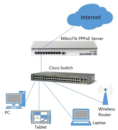
Assume, we want to emulate a 128Kibps download and 64Kibps upload line, connecting IP network 192.168.0.0/24. The network is served through the Local interface of customer's router. The basic network setup is in the following diagram:

To solve this situation, we will use simple queues.
IP addresses on MikroTik router:
[admin@MikroTik] ip address> print
Flags: X - disabled, I - invalid, D - dynamic
 #   ADDRESS            NETWORK         BROADCAST       INTERFACE
 0   192.168.0.254/24   192.168.0.0     192.168.0.255   Local
 1   10.5.8.104/24      10.5.8.0        10.5.8.255      Public
[admin@MikroTik] ip address>
And routes:
[admin@MikroTik] ip route> print
Flags: X - disabled, A - active, D - dynamic, 
C - connect, S - static, r - rip, b - bgp, o - ospf, m - mme, 
B - blackhole, U - unreachable, P - prohibit 
 #      DST-ADDRESS        PREF-SRC        G GATEWAY         DIS INTE...
 0 A S  0.0.0.0/0                          r 10.5.8.1        1   Public
 1 ADC  10.5.8.0/24        10.5.8.104                        0   Public
 2 ADC  192.168.0.0/24     192.168.0.254                     0   Local
[admin@MikroTik] ip route>
Add a simple queue rule, which will limit the download traffic to 128Kib/s and upload to 64Kib/s for clients on the network 192.168.0.0/24, served by the interface Local:
[admin@MikroTik] queue simple> add name=Limit-Local interface=Local \
\... target-address=192.168.0.0/24 max-limit=65536/131072
[admin@MikroTik] queue simple> print
Flags: X - disabled, I - invalid, D - dynamic
 0    name="Limit-Local" target-addresses=192.168.0.0/24 dst-address=0.0.0.0/0
      interface=Local parent=none priority=8 queue=default/default
      limit-at=0/0 max-limit=65536/131072 total-queue=default
[admin@MikroTik] queue simple>
The max-limit parameter cuts down the maximum available bandwidth. From the clients' point of view, the value 65536/131072 means that they will get maximum of 131072bps for download and 65536bps for upload. The target-addresses parameter defines the target network (or networks, separated by a comma) to which the queue rule will be applied.
Now see the traffic load:
[admin@MikroTik] interface> monitor-traffic Local
  received-packets-per-second: 7
       received-bits-per-second: 68kbps
        sent-packets-per-second: 13
           sent-bits-per-second: 135kbps

[admin@MikroTik] interface>
Probably, you want to exclude the server from being limited, if so, add a queue for it without any limitation (max-limit=0/0 which means no limitation) and move it to the beginning of the list:
[admin@MikroTik] queue simple> add name=Server target-addresses=192.168.0.1/32 \
\... interface=Local
[admin@MikroTik] queue simple> print
Flags: X - disabled, I - invalid, D - dynamic
 0    name="Limit-Local" target-addresses=192.168.0.0/24 dst-address=0.0.0.0/0
      interface=Local parent=none priority=8 queue=default/default
      limit-at=0/0 max-limit=65536/131072 total-queue=default

 1    name="Server" target-addresses=192.168.0.1/32 dst-address=0.0.0.0/0
      interface=Local parent=none priority=8 queue=default/default
      limit-at=0/0 max-limit=0/0 total-queue=default
[admin@MikroTik] queue simple> mo 1 0
[admin@MikroTik] queue simple> print
Flags: X - disabled, I - invalid, D - dynamic
 0    name="Server" target-addresses=192.168.0.1/32 dst-address=0.0.0.0/0
      interface=Local parent=none priority=8 queue=default/default
      limit-at=0/0 max-limit=0/0 total-queue=default

 1    name="Limit-Local" target-addresses=192.168.0.0/24 dst-address=0.0.0.0/0
      interface=Local parent=none priority=8 queue=default/default
      limit-at=0/0 max-limit=65536/131072 total-queue=default
[admin@MikroTik] queue simple>

Queue Tree Example With Masquerading

In the previous example we dedicated 128Kib/s download and 64Kib/s upload traffic for the local network. In this example we will guarantee 256Kib/s download (128Kib/s for the server, 64Kib/s for the Workstation and also 64Kib/s for the Laptop) and 128Kib/s for upload (64/32/32Kib/s, respectivelly) for local network devices. Additionally, if there is spare bandwidth, share it among users equally. For example, if we turn off the laptop, share its 64Kib/s download and 32Kib/s upload to the Server and Workstation.
When using masquerading, you have to mark the outgoing connection with new-connection-mark and take the mark-connection action. When it is done, you can mark all packets which belong to this connection with the new-packet-mark and use the mark-packet action.

  1. At first, mark the Server's download and upload traffic. With the first rule we will mark the outgoing connection and with the second one, all packets, which belong to this connection:
    [admin@MikroTik] ip firewall mangle> add src-address=192.168.0.1/32 \
    \... action=mark-connection new-connection-mark=server-con chain=prerouting
    [admin@MikroTik] ip firewall mangle> add connection-mark=server-con \
    \... action=mark-packet new-packet-mark=server chain=prerouting
    [admin@MikroTik] ip firewall mangle> print
    Flags: X - disabled, I - invalid, D - dynamic
     0   chain=prerouting src-address=192.168.0.1 action=mark-connection
         new-connection-mark=server-con
    
     1   chain=prerouting connection-mark=server-con action=mark-packet
         new-packet-mark=server
    [admin@MikroTik] ip firewall mangle>
  2. The same for Laptop and Workstation:
    [admin@MikroTik] ip firewall mangle> add src-address=192.168.0.2 \
    \... action=mark-connection new-connection-mark=lap_works-con chain=prerouting
    [admin@MikroTik] ip firewall mangle> add src-address=192.168.0.3 \
    \... action=mark-connection new-connection-mark=lap_works-con chain=prerouting
    [admin@MikroTik] ip firewall mangle> add connection-mark=lap_works-con \
    \... action=mark-packet new-packet-mark=lap_work chain=prerouting
    [admin@MikroTik] ip firewall mangle> print
    Flags: X - disabled, I - invalid, D - dynamic
     0   chain=prerouting src-address=192.168.0.1 action=mark-connection
         new-connection-mark=server-con
    
     1   chain=prerouting connection-mark=server-con action=mark-packet
         new-packet-mark=server
    
     2   chain=prerouting src-address=192.168.0.2 action=mark-connection
         new-connection-mark=lap_works-con
    
     3   chain=prerouting src-address=192.168.0.3 action=mark-connection
         new-connection-mark=lap_works-con
    
     4   chain=prerouting connection-mark=lap_works-con action=mark-packet
         new-packet-mark=lap_work
    [admin@MikroTik] ip firewall mangle>
    As you can see, we marked connections that belong for Laptop and Workstation with the same flow.
  3. In /queue tree add rules that will limit Server's download and upload:
    [admin@MikroTik] queue tree> add name=Server-Download parent=Local \
    \... limit-at=131072 packet-mark=server max-limit=262144
    [admin@MikroTik] queue tree> add name=Server-Upload parent=Public \
    \... limit-at=65536 packet-mark=server max-limit=131072
    [admin@MikroTik] queue tree> print
    Flags: X - disabled, I - invalid
     0   name="Server-Download" parent=Local packet-mark=server limit-at=131072
         queue=default priority=8 max-limit=262144 burst-limit=0
         burst-threshold=0 burst-time=0s
    
     1   name="Server-Upload" parent=Public packet-mark=server limit-at=65536
         queue=default priority=8 max-limit=131072 burst-limit=0
         burst-threshold=0 burst-time=0s
    [admin@MikroTik] queue tree>
    And similar config for Laptop and Workstation:
    [admin@MikroTik] queue tree> add name=Laptop-Wkst-Down parent=Local \
    \... packet-mark=lap_work limit-at=65535 max-limit=262144
    [admin@MikroTik] queue tree> add name=Laptop-Wkst-Up parent=Public \
    \... packet-mark=lap_work limit-at=32768 max-limit=131072
    [admin@MikroTik] queue tree> print
    Flags: X - disabled, I - invalid
     0   name="Server-Download" parent=Local packet-mark=server limit-at=131072
         queue=default priority=8 max-limit=262144 burst-limit=0
         burst-threshold=0 burst-time=0s
    
     1   name="Server-Upload" parent=Public packet-mark=server limit-at=65536
         queue=default priority=8 max-limit=131072 burst-limit=0
         burst-threshold=0 burst-time=0s
    
     2   name="Laptop-Wkst-Down" parent=Local packet-mark=lap_work limit-at=65535
         queue=default priority=8 max-limit=262144 burst-limit=0
         burst-threshold=0 burst-time=0s
    
     3   name="Laptop-Wkst-Up" parent=Public packet-mark=lap_work limit-at=32768
         queue=default priority=8 max-limit=131072 burst-limit=0
         burst-threshold=0 burst-time=0s
    [admin@MikroTik] queue tree>

Equal bandwidth sharing among users

This example shows how to equally share 10Mibps download and 2Mbps upload among active users in the network 192.168.0.0/24. If Host A is downloading 2 Mbps, Host B gets 8 Mbps and vice versa. There might be situations when both hosts want to use maximum bandwidth (10 Mbps), then they will receive 5 Mbps each, the same goes for upload. This setup is also valid for more than 2 users.

At first, mark all traffic, coming from local network 192.168.0.0/24 with a mark users:
/ip firewall mangle add chain=forward src-address=192.168.0.0/24 \
   action=mark-connection new-connection-mark=users-con
/ip firewall mangle add connection-mark=users-con action=mark-packet \
   new-packet-mark=users chain=forward
Now we will add 2 new PCQ types. The first, called pcq-download will group all traffic by destination address. As we will attach this queue type to the Local interface, it will create a dynamic queue for each destination address (user) which is downloading to the network 192.168.0.0/24. The second type, called pcq-upload will group the traffic by source address. We will attach this queue to the Public interface so it will make one dynamic queue for each user who is uploading to Internet from the local network 192.168.0.0/24.
/queue type add name=pcq-download kind=pcq pcq-classifier=dst-address
/queue type add name=pcq-upload kind=pcq pcq-classifier=src-address
Finally, make a queue tree for download traffic:
/queue tree add name=Download parent=Local max-limit=10240000
/queue tree add parent=Download queue=pcq-download packet-mark=users
And for upload traffic:
/queue tree add name=Upload parent=Public max-limit=2048000
/queue tree add parent=Upload queue=pcq-upload packet-mark=users
Note! If your ISP cannot guarantee you a fixed amount of traffic, you can use just one queue for upload and one for download, attached directly to the interface:
/queue tree add parent=Local queue=pcq-download packet-mark=users
/queue tree add parent=Public queue=pcq-upload packet-mark=users


fonte: http://wirelessconnect.eu/articles/bandwidth%20_control