As novas regras do Marco Civil da Internet
* Marcos Bruno
Em 11
de maio de 2016, como um dos últimos atos do governo Dilma Rousseff
antes do afastamento determinado pela decisão do Senado Federal, foi
promulgado o Decreto 8.771/2016, que regulamenta as disposições do Marco
Civil da Internet.
A regulamentação traz regras relacionadas a
neutralidade de rede, proteção da privacidade e de dados pessoais, e
atribuiu competências para a fiscalização do cumprimento.
E agora? Entenda as novas regras, nesse breve resumo.
• Do que trata?
Hipóteses
admitidas de discriminação de pacotes de dados na internet e de
degradação de tráfego, indica procedimentos para guarda e proteção de
dados por provedores de conexão e de aplicações, aponta medidas de
transparência na requisição de dados cadastrais pela administração
pública e estabelece parâmetros para fiscalização e apuração de
infrações previstas no Marco Civil da Internet.
• Quando passa a valer?
A partir de 10 de junho de 2016.
• A quem se aplica?
Aos
responsáveis pela transmissão, comutação e roteamento, o que inclui os
backbones, e aos provedores de conexão e de aplicação, em geral.
• A quem não se aplica?
Serviços
de telecomunicações que não envolvam conexão à Internet, e serviços
especializados, ainda que utilizem tecnologia TCP/IP, como é o caso, por
exemplo, de links dedicados privados, desde que não acedam à Internet,
de forma pública e irrestrita.
• Como ficou a neutralidade de rede?
Discriminação
ou degradação do tráfego como medidas excepcionais, em decorrência de
requisitos técnicos, ou visando priorização de serviços de emergência.
Obriga
as empresas a quem se aplica o decreto a: tratar questões de segurança
da rede, restringir envio de spam, controlar ataques de negação do
serviço (DDoS), e tratar situações especiais de congestionamento da
rede, inclusive provendo rotas alternativas, no caso de interrupção da
rota principal, ou situações de emergência.
Obrigatoriedade de
observância da regulação da ANATEL e das diretrizes estabelecidas pelo
CGI.br, nas ações de gerenciamento da rede.
Divulgação, inclusive
com obrigatoriedade de indicação nos contratos de prestação de
serviços, dos motivos que possam implicar em discriminação ou degradação
do tráfego, em linguagem de fácil compreensão.
Estabelecimento
de situações taxativas para degradação ou discriminação do tráfego em
razão de serviços de emergência, que ficam restritas a: comunicação
destinada aos prestadores de serviços de emergência ou comunicação entre
eles, ou comunicações necessárias para informar a população em
situações de risco de desastre, emergência, ou estado de calamidade
pública.
Garantia da gratuidade da transmissão de dados relacionada a serviços de emergência.
Vedação
de acordos que possam comprometer o caráter público e irrestrito da
internet no Brasil, priorizem pacotes de dados em razão de arranjos
comerciais, ou privilegiem aplicações ofertadas pelo próprio responsável
pela transmissão, comutação, ou roteamento, ou empresas do seu grupo.
As
ofertas comerciais de acesso à Internet deverão sempre privilegiar uma
internet única, de natureza aberta, plural e diversa, visando inclusão e
não discriminação.
• Como ficou a proteção da privacidade?
Autoridades
administrativas (polícia, ministério público, e outros órgãos) que
solicitem acesso a dados cadastrais de usuários da Internet deverão
indicar o fundamento legal expresso de sua competência, a motivação para
o pedido, e os indivíduos cujos dados são requeridos, vedando pedidos
genéricos ou inespecíficos.
Abre a possibilidade de o provedor
não coletar dados cadastrais como qualificação pessoal (nome, prenome,
estado civil e profissão), filiação e endereço, ficando desobrigado do
fornecimento desses dados, na hipótese de não coletar.
Os órgãos
da administração pública federal deverão publicar, anualmente, na
Internet, dados estatísticos de requisição de dados cadastrais.
Estabelece
padrões de segurança para provedores de conexão e aplicações,
relacionados à guarda e acesso dos registros de usuários da Internet,
quais sejam: (a) controle estrito do acesso aos dados; (b) mecanismos de
autenticação do acesso aos dados, permitindo individualizar o
responsável pelo tratamento dos registros; (c) registros de acesso aos
dados, contendo o momento e a duração do acesso, bem como a identidade
do responsável pelo acesso; (d) uso de soluções técnicas que garantam a
inviolabilidade dos dados, como encriptação e outras medidas
equivalentes.
Estabelecimento do princípio de retenção de dados
na menor quantidade necessária, e determinação da exclusão de tais dados
após atingida a finalidade do seu uso, ou se encerrado o prazo
determinado por obrigação legal.
Conceituação de dado pessoal
como dado relacionado à pessoa natural identificada ou identificável,
inclusive números identificativos, dados de localização, ou
identificadores eletrônicos relacionados a uma pessoa.
Obrigação
de que os dados sejam mantidos em formato interoperável e estruturado,
facilitando acesso decorrente de decisão judicial ou determinação legal.
Divulgação clara dos padrões de segurança adotados pelos provedores, preferencialmente nos próprios sites da Internet.
• Como ficou a fiscalização?
Estabelece que a Anatel atuará na regulação, na fiscalização, e na apuração de infrações.
Estabelece que a Secretaria Nacional do Consumidor atuará na fiscalização e na apuração das infrações.
Estabelece que o Sistema Brasileiro de Defesa da Concorrência atuará na apuração de infrações à ordem econômica.
Estabelece
a atuação colaborativa entre os órgãos acima, inclusive prevendo a
aplicação de sanções mesmo para as pessoas jurídicas sediadas no
exterior.
* Marcos Bruno é sócio do Opice Blum, Bruno, Abrusio e Vainzof Advogados
segunda-feira, 30 de maio de 2016
terça-feira, 24 de maio de 2016
Mikrotik - Configuração VPN L2TP no Smartphone Android
RouterOS configuration for Android L2TP/IPSec PSK VPN:
RouterOS:
/ip pool add name="VPN" ranges=10.0.0.1-10.0.0.254
/ip ipsec proposal
set [ find default=yes ] enc-algorithms=3des
add enc-algorithms=3des,aes-256-cbc name=l2tp-vpn pfs-group=none
/ppp profile
add change-tcp-mss=yes dns-server=XXX.XXX.XXX.XXX local-address=VPN name=\
l2tp-vpn remote-address=VPN
/interface l2tp-server server
set authentication=mschap2 default-profile=l2tp-vpn enabled=yes ipsec-secret=\
SECRETKEY max-mru=1460 max-mtu=1460 use-ipsec=yes
/ip ipsec policy
set (unknown) proposal=l2tp-vpn
/ppp secret
add name=USER password=PASSWORD profile=l2tp-vpn service=l2tp
/ip ipsec peer add address=0.0.0.0/0 port=500 auth-method=pre-shared-key passive=yes secret=SECRETKEY generate-policy=port-override exchange-mode=main-l2tp
send-initial-contact=yes nat-traversal=yes hash-algorithm=sha1 enc-algorithm=3des,aes-256
On Android, create a L2TP/IPSec PSK VPN.
Add the address of the VPN server and the pre-shared IPSec secret key (SECRETKEY). Don't enter a secret for L2TP or a user for IPSec.
--- Firewall
liberar portas UDP - 400, 4500, 1701:
/ip firewall filter
add chain=input comment="L2TP - Android" dst-port=500 protocol=udp
add chain=input comment="L2TP - Android" dst-port=1701 protocol=udp
add chain=input comment="L2TP - Android" dst-port=4500 protocol=udp
--- futuro: ajustar parametros e verificar acessos remotos.
segunda-feira, 23 de maio de 2016
Artigo - Review Gigabit PoE Passive
Review (Gigabit) Passive POE Injectors and Switches
A while back I tested a “dumb” active POE switch. But I still have devices which require passive POE and I don’t want a mess of cables and injectors. So I took a closer look at passive PE and what is possible with it. For this I tested some devices and you can view my review below.–Sale: I have these injectors and switches for sale! Contact me using quindor@gmail.com or IM for prices!

Passive
POE is used more often then you would expect or probably know.
Especially people who have used Mikrotik/Routerboard or Ubiquiti
products before will know what it is and what it does. It allows you to
send power over your ethernet cable to power the device it’s connected
to.
In
a sense it’s the same as active POE (802.3af/at) but then a cheaper
variant. Active POE requires active components on both sides of the link
which then negotiate what is going to happen (power or no power). So
plugging active POE into a non-POE device won’t result into the magic
smoke being released like passive POE can cause.
Passive POE in turn is a much cheaper solution then Active POE so it’s used in more low cost setups.
Gigabit Capable
Not
that long ago, passive POE was limited to 100MBit max. This was because
passive POE was using the 2 unused pairs of cable of the 4 pairs that
are available in CAT5(e). This meant that both data and power was
separated during transport.
Very
often you will see POE injectors like the following used for this. On
the origin side you have a block which takes your network cable and
power plug which then puts the power on your cable. On the other side
you again have a block which splits the power and data signal again
which you can then connect to your device.
![poe_duze[1]](https://lh3.googleusercontent.com/blogger_img_proxy/AEn0k_ucY-HeIM68uisjtu4tAdjbElFnjNx91oGOMCm6yilPMLLRbqdcQpIwmkT635zEzVVnjt0v8lMPVxmUs4dZ6NIHUBfDa0wyfxTWnsb_hj1T445UJGrMC5Qr42VAStKGg1KzNNdUM0k84inJalPg=s0-d)
Often used passive POE “injector” and “extractor” blocks for 100Mbit
This worked well for 100Mbit links but it won’t work for Gigabit links or 802.3af/at compatible equipment.
For
this a new version of passive POE has been introduced which transfers
the power over pairs which also transport data. You can still inject the
power using a block (A different version then above, you need a Gigabit
POE injector block) but the end device will have to take the power and
network out of the network cable itself so no more extractor block the
functionality has to exist in your device!
These devices can be POE version A or version B.
Version A or B?
Passive
POE comes in two variants, version A and B. The main difference between
these two is over which pairs you are receiving the power. Basically
you could say that A is the same as active POE (802.3af/at) and version B
is the passive POE standard.
Version A: Pin 1/2 Data&V- , Pin 3/6 Data&V+
Version B: Pin 4/5 Data&V+ , Pin 7/8 Data&V-
So
basically, if you have an active POE (802.3af/at) compatible device,
99% of the time you can feed it with version A passive POE and it will
run. The part that is not happening is the negotiating if power is
needed or not, the cable just always has the power turned on. This works
great, but be sure to never plug the cable into a non-POE A capable
device!
Version
B has become the passive POE standard. Equipment such as
Mikrotik/Routerboard, Openmesh and Ubiquiti uses it. Some equipment will
even accept both standards!
These
standards apply to both 100Mbit and Gigabit POE. For 100Mbit passive
POE it will accept power using the same pairs as version B does.
What voltage do I need?
For
version A this answer is simple. Active POE 802.3af/at or passively fed
version A expects 48v. Officially active POE can use between 44v and
57v but the industry standard is to feed it with 48v. This should enable
100 meter cable runs without a too high voltage drop over the cable.
Version
B is a bit more difficult. Basically, every passive POE device will
specify a voltage range it can accept. For Mikrotik/Routerboard or
Ubiquiti you are almost always safe with 24v.
A few examples:
A Mikrotik/Routerboard hAP AC accepts Gigabit passive POE version B between 11v – 57v on ether1
A Mikrotik/Routerboard CRS226 accepts Gigabit passive POE version B between 8v – 30v on ether1
A Openmesh OM2P-HS supports both 24v version B or 48v version A
A Ubiquiti UAP-AC-Lite or LR accepts Gigabit passive POE version B at 24v
A Ubiquiti UAP-AC-PRO accepts Gigabit passive POE 48v version A
A
good rule of thumb is the higher voltage you use, the better it is
because your voltage will drop less in procent compared to a lower
voltage. This also results into a higher efficiency!
24v
is a good middle voltage which is high enough to not suffer too much
voltage drop over the cable but still provide enough voltage for the
equipment on the other end.
Non passive POE devices using extractors
If
your devices do not support any form of POE natively you can use
injectors and extractors to still use the UTP cable to transport power.
This will limit your transfer speeds to 100Mbit but this can still be
useful for devices like IP camera’s or with a bit of tinkering a
raspberry Pi for instance!
Often
these will be 12v devices so be mindful that this will not work for 100
meter cable spans. Up to about 20 meters should be fine though. You
would use only the extractor block as seen in the above picture on the
device side.
What wattage do I need?
As
we all know wattage is calculated by multiplying voltage * amps. So a
24v 1A adapter will give you 24 watts. But, because of cable length
there will be voltage drop so you need to oversize your power supply a
little bit. A handy tool for this is using a voltage loss calculator.
Again for version A this is quite simple:
802.3af uses ~15 watts
802.3at uses ~30 watts
So
it’s quite easy to calculate the total wattage you are going to need
per device or for a shared injector/switch. Also because of the high 48v
voltage voltage drop is always going to be minimal even at the maximum
length of 100m.
For version B you need to calculate depending on the voltage you are injecting and the average cable length.
Calculate in voltage drop for version B
Let’s
say you are running a 100 feet/30 meter CAT5E cable using copper (No
CCA) pairs. After these 30 meters your 24v 1 Amp will be about 22.80v.
That also means that you will only have 22.80 watts at the end of the
cable. As long as your equipment is going to use less wattage then
that, it should be fine. Otherwise you will need a higher wattage power
supply or compensate for the voltage drop when injecting it (by using a
higher voltage).
Dropping
a volt or even 2 shouldn’t be too much of a problem, depending on your
starting voltage. If you are injecting 12v a drop of 1.20v drop would be
more significant! A good rule of thumb would be that dropping more then
10% of voltage will not be acceptable. That means 1.2v at 24v is 5% but
dropping 1.2v at 12v is 10% so not acceptable.
So
again, the higher voltage you can start with, the better, but make sure
your equipment will also be able to handle it. When running different
kinds of equipment with different wattage’s an average median for all
the devices will need to be chosen.
Calculating maximum wattage needed
With
that in mind, let’s say you wish to use 4x Mikrotik/Routerboard hAP AC
as access-points in your house, and they need 17 watt max a piece, you
would need to supply 68 watts total at the right voltage. Always be sure
to over dimension your power needs a little bit. A good rule of thumb
would be to add at least 25% more wattage then a maximum draw would use
so in this case that would be ~85 watts. That also means your power
supply will never run full draw continuously which will improve life
span a lot!
Passive POE injectors
Because
I wanted to test several injectors and wanted to dual-feed some
equipment (Often Mikrotik/Routerboard equipment can be fed by using the
plug (which is often 24v) and simultaneously be fed by passive POE with a
slightly higher voltage, that way you have cheap redundant power!) I
looked at several different injectors.
All these injectors have 2 special features:
–
Each injector is suited for version A and B (not at the same time).
They are equipped with two seperate voltage input plugs by which you can
decide which version of passive POE you need! Do NOT plug them both in at the same time!
–
Each port on the injectors is equipped with a 650mA to 1A fuse! If a
device has a short or something else goes wrong the port will
automatically be disabled by the fuse and re-engage when the problem is
fixed.
6 Port Gigabit injector
When you are not using a 19″ rack the 6 port Gigabit power injector is ideal.
When
feeding it with a certain voltage, let’s say 48v for version A it will
distribute the voltage parallel over all the ports. And each port can
use the wattage it needs. See the previous chapter to decide what
wattage power supply you require!
Because photos tell you more then words in this case:

6 port Gigabit injector, easy screw holes on the side to mount it to a bracket or wall.
Notice the power input sockets on both sides, that way you choose version A or B

The backside. LAN goes in the front, LAN+POE comes out of the back. Also notice the grounding wire you can use to ground it

Demonstrating version B with a hAP AC. You can easily hook up 5 or 6 to provide power with 1 adapter

Demonstrating version A with a 802.3af camera
Not much left to say about the 6 port version, next the 12 port 19″ version!
12 port 19″ Gigabit injector
This
version has all the features the 6 port version has but it’s made out
of sturdy metal with 12 ports in a convenient 19″ format allowing you to
incorporate it into your rack and have a tidy POE feed to your
equipment.

The 19″ version, also with dual input on the back

Feeding a hAP AC using version B

Running a 802.3af compliant IP camera
Not much else to be said about this version. It works great!
Passive POE switches
Other
then using a passive POE injector (if you already have a switch) you
can also use passive POE switches. This will cut down on the needed
cables even more! It’s a cheap version of a true managed active POE
switch but this is a “dumb” switch with passive POE.
These
switches still keep all the features of the injector. You can use it
with version A or B and it has the fuses installed, etc. The Gigabit
version has a switch per port with which you can choose to put that port
in mode A or B so you can feed both types of equipment with just this
one switch!
Choosing
to use a switch or not all depends on expected bandwidth usage. The
100Mbit version for instance is great when you are running IP camera’s.
Each camera is only going to use a max or 5 or 6Mbits of bandwidth so
running up to 7 of those on a single 100Mbit switch would still only use
42Mbit! Plenty of bandwidth and it will save a lot of cables compared
to an injector.
The
Gigabit version is more suited for higher bandwidth equipment such as
access-points. If you are running several N access-points having a
gigabit of bandwidth for several of them will be more then enough! If
you are running more then 2 or 3 AC access-points though I would advise
using an injector instead of switch to not create a bottleneck in
bandwidth.
7xPOE, 1xUplink 100Mbit passive POE switch
As
said above, this switch can also be used for version A or B and it also
has the fuses per port as the injectors have. Voltage input is variable
but it’s advised to either use 24v or 48v depending on your needs.

Front of the switch, port 8 is the uplink port

The back with the dual inputs for selecting version A or B passive POE

A 802.3af camera connected
7xGigabit POE, 1xGigabit uplink Gigabit passive POE switch
This
switch is very much the same as the above one but it switches at
Gigabit speeds. A unique feature of the gigabit version is that you can
selected to use no output, version A or version B per port on the back!
You can use it with a variable voltage input but 24v or 48v is
recommended.

The front of the Gigabit passive POE switch

You can select off or version A / B per port
A Mikrotik/Routerboard hAP AC using version B connected at gigabit speeds
Ending conclusion
And
that’s that. During the testing I did all the equipment I had worked
perfectly. Both version A equipment and version B equipment booted right
up and worked perfectly stable. Connecting additional devices either to
the injectors or switches did not interrupt power to the running
devices and they shared a single power supply without issue (Be sure to
size your power supply correctly, see above).
If
you want to run some IP camera’s and/or access-points at home I would
very much recommend using one of these injectors or switches to provide
them with power. Using separate injectors for each device quickly turns
into an unmanageable mess in my experience and requires a lot of power
sockets, etc. It’s just not very practical. Using an injector and
especially a switch solves this problem all together and allows you to
neatly setup everything!
Also using a single adapter often saves you power because of a more efficient conversion.
The only downside to passive POE? Never ever plug a passive POE fed network cable into a non-passive POE accepting device you
will make the magic smoke appear and most probably kill it’s network
port. If you are careful with that one downside it can be a lot cheaper
then getting official POE devices and/or switches!
fonte: http://blog.quindorian.org/2016/03/review-gigabit-passive-poe-injectors-and-switches.html/
Mikrotik - Review hAP AC
Review of the Mikrotik hAP AC and great wireless coverage in your home

This will be a short review and will mostly reflect my opinion about the device as my test results.
My primary reason of interest for the device is using it as an access-point. As written above, this is the first (and currently only) Mikrotik device that has a dual-radio setup of 2.4Ghz and 5.0Ghz AC each with 3 antenna’s attached.
Since I sold my previous access-points a while back (Ubiquiti UAP-ACv1) I have been looking for something new. They performed just fine for the time I had them (quite well actually) but since I enjoy testing out other/new technologies I decided to sell them and either get something new from Mikrotik or from Ubiquiti (Such as the UAP-AC-PRO).
Multiple Access-Points with a controller, not one big one
Since Mikrotik introduced CAPsMAN a while back I’ve been interested in it. I like the concept of having a central WiFi controller with several access-points spread throughout the house. And I figured the hAP AC would make an ideal candidate for this. In my new house I’m looking to use 3 or 4 ceiling mounted access-points spread out through the house to have good coverage and speeds everywhere!I don’t believe in $300+ consumer WiFi router/firewall/access-points with giant antenna’s located somewhere in the house to deliver WiFi to all the clients you might have, wherever they are. Especially since they now have started introducing $450+ triple-radio access-points with 2 AC radio’s. Complete madness to me and I believe they only sell because consumers think bigger is better, which, with WiFi, is NOT the case. I’d much rather have 3 low power radio access-points spread through the house then have 1 high-power one in the middle. It will give you a much better average throughput rate and better coverage all through the house.
Also remember that every WiFi device, big antenna’s or not is limited to the same amount of output power. Yes, a bigger antenna will help you receive signals, but not by as much as you would imagine. 3dB extra on your antenna does not increase your range to double the area. Also, it does not give you ANY higher output range. Because total output power is determined by maximum dB. So you can either use a bigger antenna or send more wattage in an antenna, not do both because it’s capped by law what is allowed.
And thus I would much rather have 3 access-points spread over the house which all have low output power to serve the clients near to it and have decent reception back, because the clients they are serving are never far away. Combined they will almost always be able to deliver a much higher performance then one access-point will ever manage.
Downsides? I can think of only one, you need to have cables to all the places where you wish to put those access-points. Since I’m building a new house this will not be a problem.
What to expect or radio connection quality
Another
factor of attaining the maximum amount of transfer speeds possible is
your actual radio connection to your access-point. In a perfect world
you would always connect at 1300Mbit AC speeds but in reality this is
almost never the case.
For
instance, most laptops are equipped with 2×2 AC wireless cards, not 3×3
AC. From what I know only Apple MacBook Pro’s are equipped with very
good Intel 3×3 AC adapters. Most others, having a 2×2 radio, will limit
your transfer speed and give you a maximum radio connection speed of
866Mbit.
Phones and other small devices most often only have a 1×1 AC radio limiting radio connection speeds to 433Mbit.
Next to
maximum speeds, more important is what kind of realistic speed you are
able to connect to your access-point. Even if you have a 3×3 AC wireless
card and decent antenna’s in your laptop, that still does not guarantee
you will always be getting the maximum transfer rates possible.
Distance, walls, other signals in the same band, bad software or
hardware implementations, there is lots of reasons WiFi in the end
becomes quite complicated.
Whatever you do, never use a repeater
Whatever
you do… never EVER use a wireless repeater. I can’t be more clear then
that. A wireless repeater takes an already bad/horrible WiFi signal and
rebroadcasts it so that other clients can connect to it. This
effectively halves bandwidth and doubles or triples latency. It’s a
proven unstable and inconsistent construction and even worse it destroys
the whole radio spectrum for you and everyone around you. Bad bad bad.
If it’s
absolutely and completely impossible to get to an ethernet cable to the
place needing better wireless coverage try using an Ethernet-over-Power
set to transfer ethernet to it that way. That is still a much better
solution then using a wireless repeater and almost always a faster way
to do it too.
The hAP AC as an access-point without CAPsMAN
With all that theory out of the way, the hAP AC tests!
When I
received my hAP AC’s I deployed them in a similar setup as my current
Mikrotik N access-points were setup. I’ve been using self built 3×3
5.0Ghz Mikrotik RB912UAG-2HPnD before this. So in theory this gave me
450Mbps of bandwith, in reality this was around 100Mbit to max 150Mbit
though. Fairly stable and ok, but not that great as a “cable
replacement” what I was using it for in my current home.
The results
below are pretty good as an improvement over my previous setup but it
also immediately highlights the bottleneck of the hAP AC in such a
situation.
Please
remember that these tests where done using conditions which where
specifically setup in such a way that it would maximize transfer rates.
That means access-points close together, no other clients connected,
etc.
Max transfer speeds
hAP AC to hAP AC
Both running RouterOS v6.35rc12 with wireless-rep package
Pseudobridge to AP Bridge
(I connect
my desktop 1Gbit NIC to the first hAP AC which in turns connects to
another hAP AC wirelessly which is in normal access-point mode)
Speedtest.net
Ping: 8ms
Download: 184Mbit / 23MB/sec (My connection is 200Mbit max)
Upload: 19Mbit / 2,37MB/sec (My connection is 20Mbit max)
CPU Usage peak during download: 50%
(All tests done using iperf2)
iperf -c 10.10.128.254 -w 1MB -r -t 30 -P 1
Download: 484Mbit / 60,5MB/sec
Upload: 440Mbit / 55MB/sec
CPU Usage peak during download: 98%
CPU Usage peak during upload: 47%
iperf -c 10.10.128.254 -w 1MB -r -t 30 -P 4
Download: 498Mbit / 62,25MB/sec
Upload: 452Mbit / 56,5/MB/sec
CPU Usage peak during download: 99%
CPU Usage peak during upload: 54%
iperf -c 10.10.128.254 -w 1MB -r -t 30 -P 8
Download: 500Mbit / 62,50MB/sec
Upload: 444Mbit / 55,5/MB/sec
CPU Usage peak during download: 99%
CPU Usage peak during upload: 58%
iperf -c 10.10.128.254 -w 1MB -r -t 30 -P 16
Download: 505Mbit / 63,13MB/sec
Upload: 455Mbit / 56,90MB/sec
CPU Usage peak during download: 10%
CPU Usage peak during upload: 58%
And there
you have it! In a maximum performance setup connecting two hAP AC’s
together their maximum transfer rate is about 500Mbit because of CPU
limitations. Weirdly enough, the CPU usage between upload or download on
an hAP AC shows a very different amount of CPU usage. I’m not sure if
this is by design or something in RouterOS causing it.
Ok, that
means that with the current software, the hAP AC will never be able to
achieve it’s 3×3 AC radio maximum a 1300Mbit link would allow for.
Realistically and the highest I’ve ever seen in a review that would
result in a transfer of about ~700Mbit / 87,50MB/sec. So the hAP AC is
not that far off but still, strictly speaking it is CPU limited.
Interpreting those results for my intended situation
I believe
those results to be good for what the hAP AC is. Is the hAP AC the best
AC access-point the world has ever seen? No, certainly not. I would call
it average to good, leaning to good. I believe it will only become
excellent for me when I take the price, RouterOS, continued upgrades and
CAPsMAN into the equation. Your situation might differ though!
More rants about ‘spider’ access-points
As I stated
above, I will be using it mainly in a multiple access-point deployment
situation. In such a case, not being able to hit the absolute maximum in
performance is compensated by having multiple access-points which can
handle clients at the same time literally doubling or tripling your
potential throughput.
I know, I
know, it doesn’t actually work that way. They will be in different
area’s and not servering the same client. That doesn’t seem to stop some
vendors with indoctrinating their consumers with it though. If I would
follow the rules vendors use on their packaging with 4 access-points
that would be 7000Mbit wireless!
Of course it doesn’t work that way but that doesn’t stop them from shouting those numbers it would seem? Like this giant 8 antenna spider access-point.
I’m sure it’s a great access-point, but AC5300? Nope, one client can
still only connect to one radio. And how do you uplink this beast? 2
cables? My 4 access-points would have 4 separate dedicated Gigabit
links, that’s more then double the bandwidth! Muhahaha. No, but
seriously. That Asus costs 450 euro! That’s enough to buy 3 hAP AC’s!
I’m not saying it’s a bad access-point, just more often then not, not
the right solution.
Realistic throughput
When
testing further using the same setup and with different clients I
believe the radio and antenna’s in the hAP AC to be fair. It’s using 2dB
internal antenna’s which isn’t bad, but also not the best. Again, in my
case this will be fine because I plan on using multiple access-points
spread out through the house, but if you where looking at a single hAP
AC to provide coverage for your whole 2 story house, it might not be the
best access-point for you. I believe it will do it, but further away
and through some walls you won’t be achieving record braking speeds
anymore and even further away some blackout spots may occur.
Adding CAPsMAN into the mix
In the end I want to use CAPsMAN to manage my hAP AC’s so that was the next test I did.
There
is two modes you can run your CAPsMAN access-points. Local breakout or
tunneling all your traffic to your CAPsMAN controller (A CCR1009 in my
case) and breaking it out there. For me, the last variant is the most desirable.
I
will have multiple SSID’s and breaking them all out locally will
involve running VLAN’s over the network and bridging all those together
on the separate access-points.
With central breakout all the traffic of the access-points will be
tunneled to the central CAPsMAN controller and broken out there. Much
easier to manage!
CAPsMAN mode with central breakout
But, there
is a downside to using the tunneled central breakout method, higher CPU
load. In testing using CAPsMAN lowered the attainable transfer speed to
about ~300Mbit of actual throughput before running into a CPU limit on
the hAP AC.
On a funny
note, it actually depends on which way the traffic is going, uploading
from your client to the hAP AC is actually going to be faster up to
about ~380Mbit because it’s a lower CPU load on the hAP AC.
You need to decide for yourself if you are going to accept the lowered maximum transfer rate or not.
Other then
the maximum transfer rated being capped by the central breakout mode it
has performed very well the last two days I’ve been using it as my
“production” access-point in my home!
It hasn’t
dropped a ping yet, latency is great and all my devices are connected to
it without issue. Transfer rates are a lot faster then my N
access-points before (even 5.0Ghz one’s) and the CPU mostly isn’t my
bottleneck but the radio connection is. I’m pretty happy with it!
CAPsMAN with local breakout
I haven’t gotten around to testing the hAP AC in local breakout mode yet. I will be doing so soon and update this review.
The hAP AC as a router/firewall and access-point
All of what
I’ve written before has been about using the hAP AC as a dedicated
access-point. Of course, as with any Mikrotik Routerboard/RouterOS
device you have the full power of RouterOS available. It does have 5
Gigabit ethernet ports!
Although
the hAP AC will do both functions (router/firewall and access-point)
without any issues technically as we learned above using it as an
access-point only the CPU will become even more of an issue. I
believe you will probably be fine with some simple firewall rules and
internet connections up to 200Mbit and getting those speeds over AC
WiFi. Anything more then that and the CPU will probably become your
limiting factor again. More about this when I’m able to do some tests.
I did some cabled tests to my own network to see what kind of performance the hAP AC can give you while using it as your router/gateway AND access-point at the same time.
First the cabled tests, although it was configured as an access-point also, it did not have any clients connected.
Gateway tests
Wired, NAT, No Fasttrack
Speedtest.net
Ping: 8ms
Download: 190Mbit / 23,75MB/sec (My connection is 200Mbit max)
Upload: 19Mbit / 2,37MB/sec (My connection is 20Mbit max)
CPU Usage peak during download: 22%
(All tests done using iperf3)
iperf -c 10.10.128.254 -w 1MB -t 30 -P 1 (with or without -R)
Download: 827Mbit / 103,37MB/sec
Upload: 849Mbit / 106,12MB/sec
CPU Usage peak during download: 100%
CPU Usage peak during upload: 100%
iperf -c 10.10.128.254 -w 1MB -t 30 -P 4 (with or without -R)
iperf -c 10.10.128.254 -w 1MB -t 30 -P 4 (with or without -R)
Download: 756Mbit / 94,50MB/sec
Upload: 801Mbit / 100,12MB/sec
CPU Usage peak during download: 100%
CPU Usage peak during upload: 100%
iperf -c 10.10.128.254 -w 1MB -t 30 -P 8 (with or without -R)
Download: 735Mbit / 91,87MB/sec
Upload: 803Mbit / 100,37MB/sec
CPU Usage peak during download: 100%
CPU Usage peak during upload: 100%
iperf -c 10.10.128.254 -w 1MB -t 30 -P 16 (with or without -R)
Download: 715Mbit / 89,37MB/sec
Upload: 793Mbit / 99,12MB/sec
CPU Usage peak during download: 100%
CPU Usage peak during upload: 100%
As you can
see, without Fasttrack the hAP AC is capable of almost routing and
NAT’ting a Gigabit in software mode. The more connections I created the
slower it got because the CPU was the limiting factor.Next are the same tests but with Fasttrack enabled. The rest of the settings are exactly the same.
Gateway tests
Wired, NAT, Fasttrack enabled
Speedtest.net
Ping: 8ms
Download: 190Mbit / 23,75MB/sec (My connection is 200Mbit max)
Upload: 19Mbit / 2,37MB/sec (My connection is 20Mbit max)
CPU Usage peak during download: 16%
(All tests done using iperf3)
iperf -c 10.10.128.254 -w 1MB -t 30 -P 1 (with or without -R)
Download: 902Mbit / 112,75MB/sec
Upload: 903Mbit / 112,87MB/sec
CPU Usage peak during download: 63%
CPU Usage peak during upload: 63%
iperf -c 10.10.128.254 -w 1MB -t 30 -P 4 (with or without -R)
Download: 910Mbit / 113,75MB/sec
Upload: 910Mbit / 113,75MB/sec
CPU Usage peak during download: 65%
CPU Usage peak during upload: 65%
iperf -c 10.10.128.254 -w 1MB -t 30 -P 8 (with or without -R)
Download: 911Mbit / 113,87MB/sec
Upload: 906Mbit / 113,25MB/sec
CPU Usage peak during download: 73%
CPU Usage peak during upload: 68%
iperf -c 10.10.128.254 -w 1MB -t 30 -P 16 (with or without -R)
Download: 908Mbit / 113,50MB/sec
Upload: 909Mbit / 113,62MB/sec
CPU Usage peak during download: 80%
CPU Usage peak during upload: 69%
iperf -c 10.10.128.254 -w 1MB -t 30 -P 80 (with or without -R)
Download: 943Mbit / 117,87MB/sec
Upload: 912Mbit / 114,00MB/sec
CPU Usage peak during download: 85%
CPU Usage peak during upload: 70%
Fasttrack makes a noticeable difference in maximum throughput performance. It can now sustain a Gigabit routed and NAT’ted without topping out the CPU. It can probably handle some rules with it.
Next I took another hAP AC, put it into pseudobridge mode and connected it using wireless to the hAP AC doing all the other tasks. In theory this is comparable as having a client connect to the access-point.
Well that is
surprising? Even while routing and doing NAT the hAP AC remains exactly
as fast as not doing those tasks! Either some parts of the software
still need to be fixed or it just works because of fasttrack, I don’t
know right now. It just does surprisingly well doing both tasks at the
same time.
Power consumption
In doing some tests I judge idle wattage to be around 3 to 4 watt. The max power usage I don’t know yet, but the data given is confusing while the little paper included with the hAP AC in the box says 5 watt. I’m inclined to believe the max 17 watt because the adapter that comes with it is a 24v 1.2A one, that equates to 28.8 watt. Mikrotik also uses 24v 0.8A (19.2 watt) and 24v 0.38A (9.12 watt) adapters. If the stated 5 watt would be correct, they would have included a lower amperage adapter so I’m thinking 17 watt is the correct max value.
Fasttrack makes a noticeable difference in maximum throughput performance. It can now sustain a Gigabit routed and NAT’ted without topping out the CPU. It can probably handle some rules with it.
Next I took another hAP AC, put it into pseudobridge mode and connected it using wireless to the hAP AC doing all the other tasks. In theory this is comparable as having a client connect to the access-point.
Gateway tests
Wireless, NAT, Fasttrack enabled
Wireless, NAT, Fasttrack enabled
Speedtest.net
Ping: 8ms
Download: 190Mbit / 23,75MB/sec (My connection is 200Mbit max)
Upload: 19Mbit / 2,37MB/sec (My connection is 20Mbit max)
CPU Usage peak during download: 50%
(All tests done using iperf3)
iperf -c 10.10.128.254 -w 1MB -t 30 -P 4 (with or without -R)
Download: 495Mbit / 61,87MB/sec
Upload: 451Mbit / 56,37MB/sec
CPU Usage peak during download: 66%
CPU Usage peak during upload: 97%
iperf -c 10.10.128.254 -w 1MB -t 30 -P 16 (with or without -R)
Download: 519Mbit / 64,87MB/sec
Upload: 472Mbit / 60,25MB/sec
CPU Usage peak during download: 80%
CPU Usage peak during upload: 99%
iperf -c 10.10.128.254 -w 1MB -t 30 -P 100 (with or without -R)
Download: 563Mbit / 70,37MB/sec
Upload: 480Mbit / 60,00MB/sec
CPU Usage peak during download: 90%
CPU Usage peak during upload: 99%
Power consumption
In doing some tests I judge idle wattage to be around 3 to 4 watt. The max power usage I don’t know yet, but the data given is confusing while the little paper included with the hAP AC in the box says 5 watt. I’m inclined to believe the max 17 watt because the adapter that comes with it is a 24v 1.2A one, that equates to 28.8 watt. Mikrotik also uses 24v 0.8A (19.2 watt) and 24v 0.38A (9.12 watt) adapters. If the stated 5 watt would be correct, they would have included a lower amperage adapter so I’m thinking 17 watt is the correct max value.
Some photo’s of the device
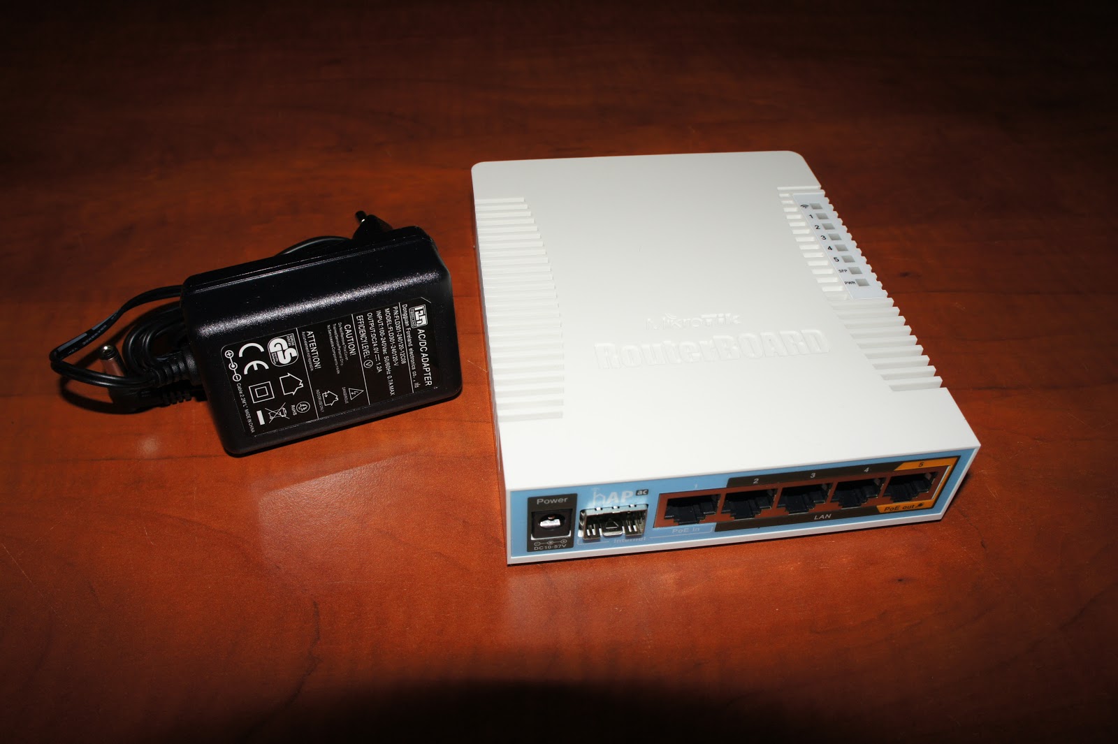
 It comes in a neat tiny box
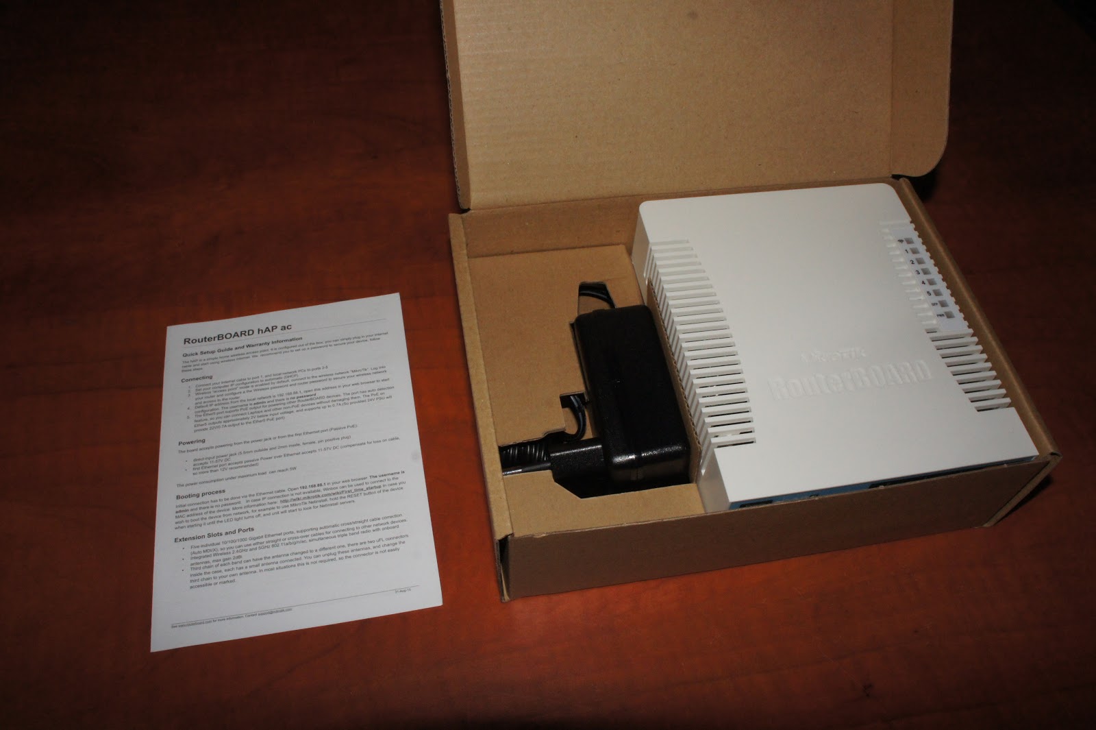 All the hAP AC’s come bundled with a 24v 1.2A power adapter
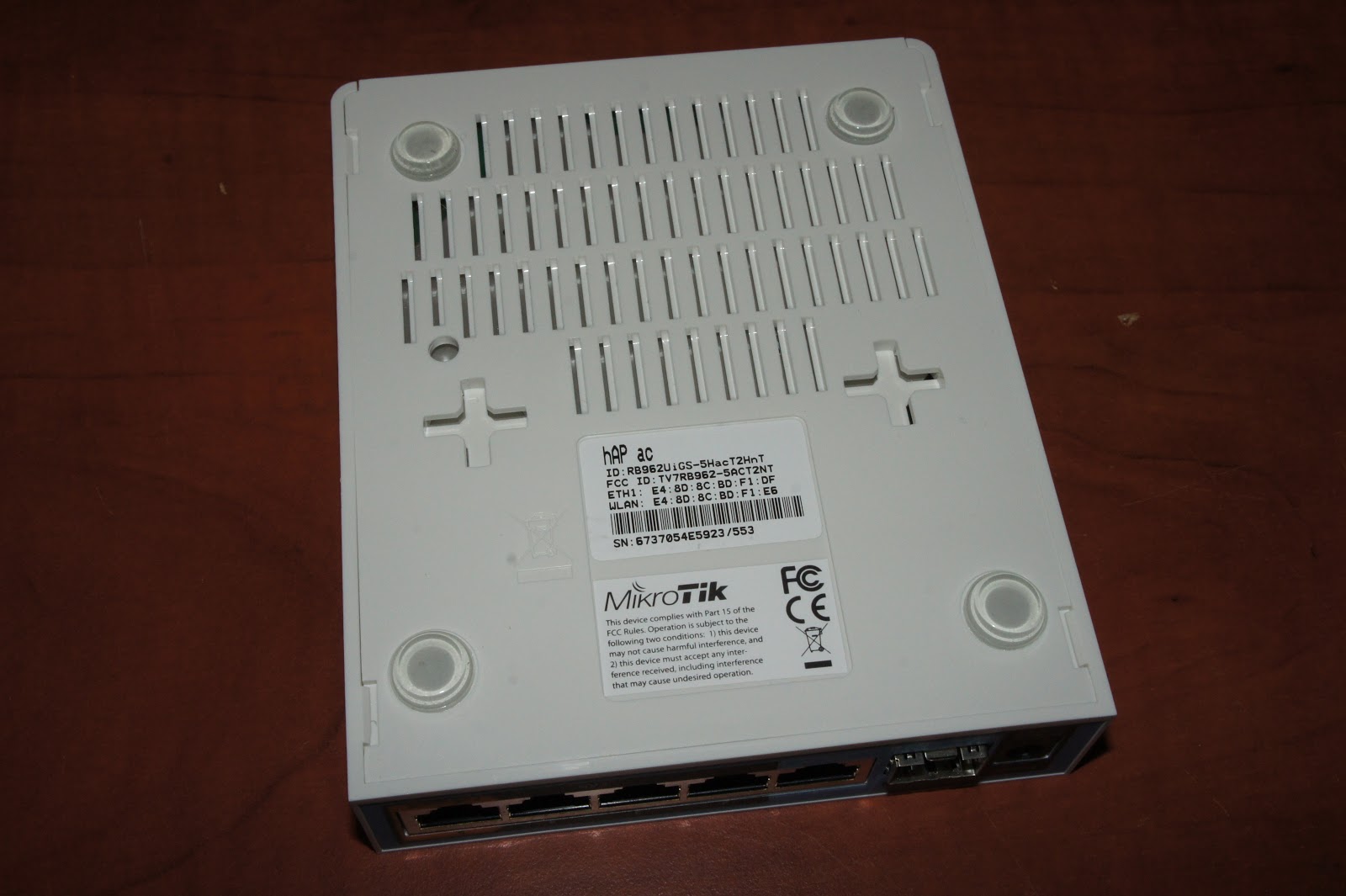 The backside of the chassis, plenty of holes for ventilation
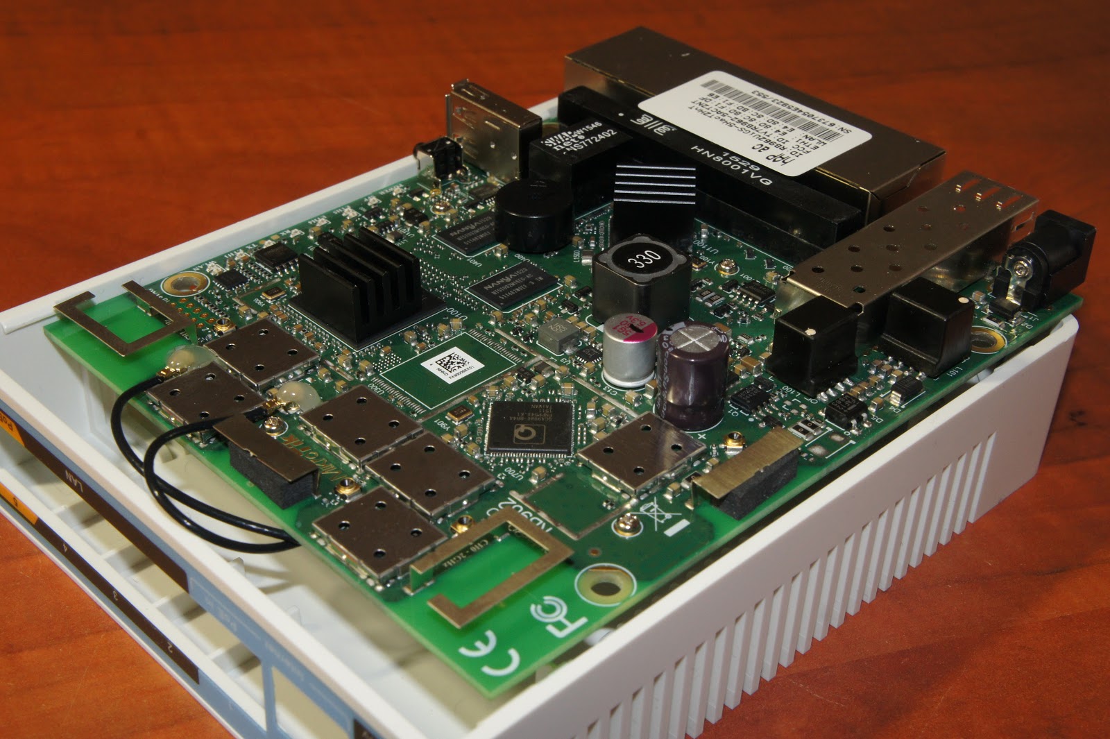 An overview of the board inside
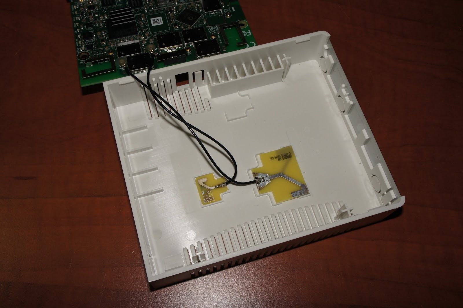 The ‘external’ antenna’s inside the case. You could hook up different one’s if you want
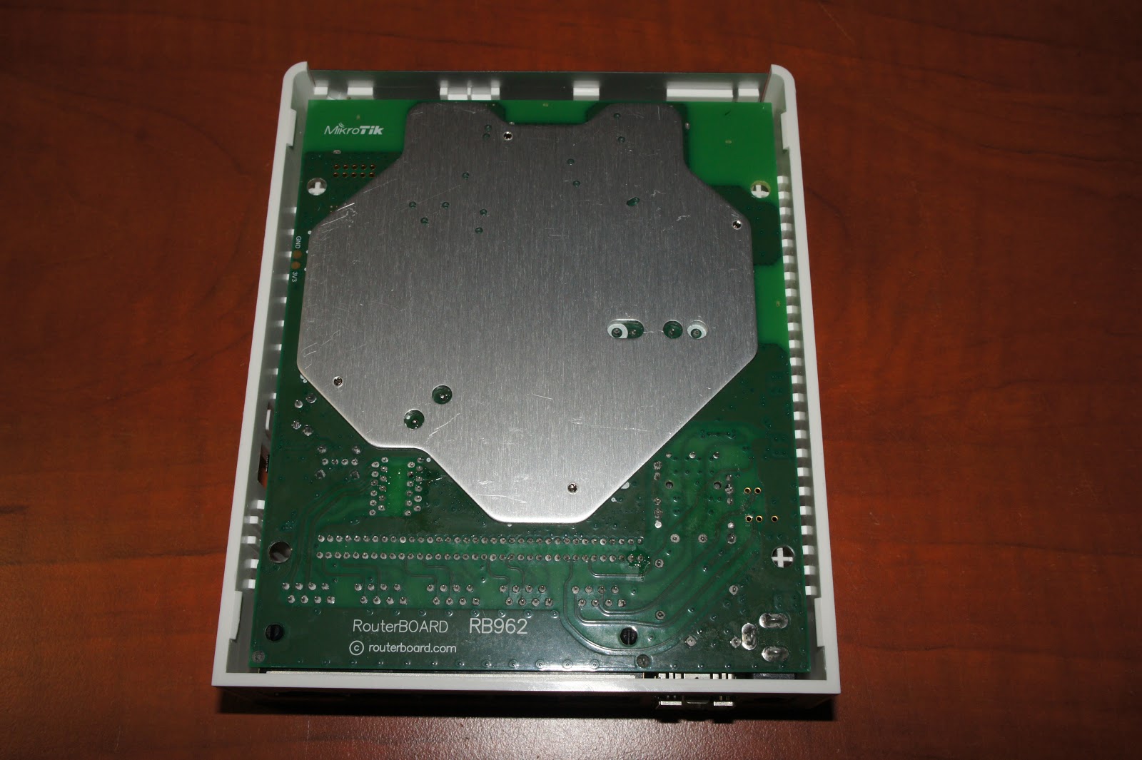 Plenty of shielding on the backsize
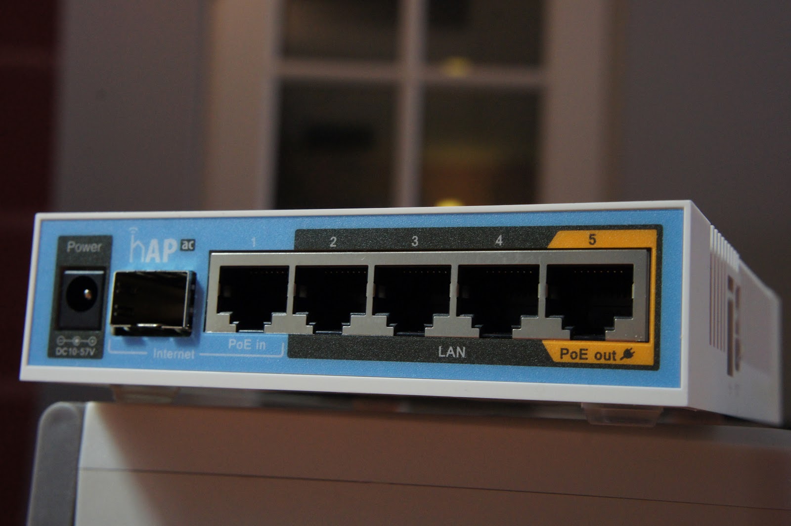 The front with a power socket, SFP slot and 5x Gigabit with POE in and out
Concluding remarks
I believe
the hAP AC does pretty good as an access-point. Yes there is better to
be had, but those will also cost (a lot) more. The closest competitor
that I know of would be the Ubiquiti UAP-AC-PRO. That one is a little
bit more expensive though and has had it’s own share of throughput
issues (With only recent alpha firmware raising the max throughput of
~500MBit to around ~600Mbit). Who knows that might also happen with the
hAP AC later on since it’s based around practically the same hardware.
Surprisingly it also does very well combining the role of a router/firewall and access-point together. No slowdown was seen even when downloading over wireless going through NAT! Very surprising but the numbers don’t lie. If you have an internet connection with a max of 300Mbit or even a little bit more (Up to 500Mbit?) it will actually do quite well it seems!
Surprisingly it also does very well combining the role of a router/firewall and access-point together. No slowdown was seen even when downloading over wireless going through NAT! Very surprising but the numbers don’t lie. If you have an internet connection with a max of 300Mbit or even a little bit more (Up to 500Mbit?) it will actually do quite well it seems!
I suspect
Mikrotik will be introducing a wAP AC and cAP AC soon being the same
hardware in a different form factor to further their line of
access-points to be used with CAPsMAN. If you wish to mount the current
hAP AC on the ceiling or wall you could use an RFelements Stationbox
Spot hiding all the LEDs, cable and providing a bit cleaner look.
But all in
all I’m happy with the little device. It does very well for it’s price
and it’s been perfectly stable for me which is also a very important
factor. No sudden disconnects, ping drops or broken connections. A
perfect setup for a larger home and all managed using my central
CCR1009!
fonte: http://blog.quindorian.org/2016/02/review-of-mikrotik-hap-ac-and-great.html/
https://forum.mikrotik.com/viewtopic.php?f=2&t=112627
https://forum.mikrotik.com/viewtopic.php?f=2&t=112627
Avaliar - acesso remoto
http://www.mikogo.com
http://info.abril.com.br/downloads/crossloop
www.superacessoremoto.com
http://beebom.com/teamviewer-alternatives/
http://www.cooperati.com.br/2013/07/11/cuidado-invasao-com-ammy-admin-software-conexao-remota/
Sem dúvida (talvez por ser bem conhecido no mercado) o Teamviewer é o software campeão naquilo que faz: Acessar, gerenciar e dar suporte a computadores remotamente. Hoje apresentaremos 5 softwares alternativos que assim como o TeamViewer que também dão conta do recado e têm as mesmas características.

Ammyy Admin
Altamente confiável além de ser uma ferramenta amigável para controlar ou obter acesso remoto ao computador. Com este software, você pode fornecer um suporte de administração remota, assistência aos seus clientes ou usuários.
 Ammyy Admin
LogmeIn
Esqueceu um documento importante? Transfira-o. Não pode enviar por email um arquivo grande? Compartilhe-o. Precisa de uma cópia impressa de casa? Imprima na gráfica mais próxima. Disponível para Windows, Mac OS e IPad.

LogmeIn
CrossLoop
Este software é gratuito e tem um recurso de compartilhamento de tela totalmente funcional e está disponível tanto para Windows quanto para Mac OS.

CrossLoop
Gbridge
Este é completamente gratuito que permite controlar remotamente o PC de uma forma eficaz, inovadora e incrível.

Gbridge
Mikogo
Mikogo é um software fácil de usar para acessar um desktop remoto. Uma solução rápida e segura para prestar suporte ou controlar o um computador remotamente. Ele permite outras opções de controle como conferências via web, reuniões on-line, seminários e muito mais.

Mikogo
Resumindo…
Estes 5 softwares similares ao Teamviewer utilizam o mesmo propósito: acessar ou gerenciar um outro PC ou dispositivo remotamente de maneira simples e rápida sem a necessidade de adquirir financeiramente outros softwares para o mesmo propósito.
fonte: http://escreveassim.com.br/2013/12/19/5-softwares-alternativos-semelhantes-ao-teamviewer/
http://info.abril.com.br/downloads/crossloop
www.superacessoremoto.com
http://beebom.com/teamviewer-alternatives/
http://www.cooperati.com.br/2013/07/11/cuidado-invasao-com-ammy-admin-software-conexao-remota/
5 Softwares alternativos semelhantes ao Teamviewer

Ammyy Admin
Altamente confiável além de ser uma ferramenta amigável para controlar ou obter acesso remoto ao computador. Com este software, você pode fornecer um suporte de administração remota, assistência aos seus clientes ou usuários.

LogmeIn
Esqueceu um documento importante? Transfira-o. Não pode enviar por email um arquivo grande? Compartilhe-o. Precisa de uma cópia impressa de casa? Imprima na gráfica mais próxima. Disponível para Windows, Mac OS e IPad.

LogmeIn
CrossLoop
Este software é gratuito e tem um recurso de compartilhamento de tela totalmente funcional e está disponível tanto para Windows quanto para Mac OS.

CrossLoop
Gbridge
Este é completamente gratuito que permite controlar remotamente o PC de uma forma eficaz, inovadora e incrível.

Gbridge
Mikogo
Mikogo é um software fácil de usar para acessar um desktop remoto. Uma solução rápida e segura para prestar suporte ou controlar o um computador remotamente. Ele permite outras opções de controle como conferências via web, reuniões on-line, seminários e muito mais.

Mikogo
Resumindo…
Estes 5 softwares similares ao Teamviewer utilizam o mesmo propósito: acessar ou gerenciar um outro PC ou dispositivo remotamente de maneira simples e rápida sem a necessidade de adquirir financeiramente outros softwares para o mesmo propósito.
fonte: http://escreveassim.com.br/2013/12/19/5-softwares-alternativos-semelhantes-ao-teamviewer/
sábado, 21 de maio de 2016
Software de Monitoramento - avaliar
http://wiki.mikrotik.com/wiki/Munin_Monitoring
http://docs.cacti.net/plugin:mikrotik
http://wiki.mikrotik.com/wiki/SNMP_PHP
https://oss.oetiker.ch/rrdtool/gallery/index.en.html
http://torrus.org/
----
http://docs.cacti.net/plugin:mikrotik
http://wiki.mikrotik.com/wiki/SNMP_PHP
https://oss.oetiker.ch/rrdtool/gallery/index.en.html
http://torrus.org/
----
Top 16 best network monitoring tools for 2016 - - Pandora FMS blog
https://blog.pandorafms.org/network-monitoring-tools/quinta-feira, 19 de maio de 2016
RRD - removendo pontos fora da curva
Removing spikes from RRD databases
 RRDs
are fixed size databases for storing time series data. They collect
information given to them and normalize it to permit trending over long
periods of time.
RRDs
are fixed size databases for storing time series data. They collect
information given to them and normalize it to permit trending over long
periods of time.Spurious data may inadvertently make it’s way into a database. Treating this data is possible using the following means:
- Set the rrd-min and/or rrd-max variable(s) for each datasource when creating new RRD databases
- Use rrdtool dump to export the RRD database to XML format, edit out the spurious values and import the data back into the RRD database
- Use rrd tune to apply rrd-min and/or rrd-max variable(s) to an existing RRD database. All values outside the minimum or maximum defined bounds will be set to NaN.
rrdtool tune--maximum :
- Use the perl script removespikes.pl. This would remove all spikes within 1% of the datapoints in the rrd file. If 1% does not fix them, modify the % value up until all the spikes are removed. Though this may eat up some valid values in the process, use with caution!
perl removespikes.pl -l 1 fastrouter_ethernet0_1.rrd
- Use rrd_editor, a cross platform win32 or perl/tk tool to seek and remove spikes in an RRD. I have not used the tool, but according to comments it works as advertised. It also lets you easily add or remove RRAs and datasources from an RRD, which is a golden feature for many of us.
- Use killspike2 an RRD spike removal script distributed as part of the Cricket network management system. I have not used the script, but it is known to work.
genDevConfig will automatically set rrd-min and rrd-max values for all config-tree targets it creates for Cricket.
fonte: http://acktomic.com/2007/08/31/removing-spikes-from-rrd-databases/
(avaliar pois é muito antigo)
---- manual
rrdtool dump filename.rrd > filename.xml
vi filename.xml
rrdtool restore filename.xml filename.rrd